Warning
This document is current with effect from the date shown on the cover page. As the International Mine Action Standards (IMAS) are subject to regular review and revision, users should consult the IMAS project website in order to verify its status at (http://www.mineactionstandards.org/, or through the UNMAS website at http://www.mineaction.org).
Copyright Notice
The International Mine Action Standards (IMAS) are owned, controlled and copyrighted by the United Nations. None of the materials provided in IMAS may be used, reproduced or disseminated, in whole or in part, in any form or by any means, without prior written permission from the United Nations acting through the United Nations Mine Action Service (UNMAS), except as set out below. None of the materials in IMAS are to be sold.
The use, reproduction or re-dissemination of IMAS by third parties, in whole or in part, is permitted provided that the United Nations is appropriately attributed and provided also that such use, reproduction or redissemination is not for commercial purposes. The United Nations may be attributed by the placement of the following text: Used and reproduced with permission of the United Nations.
Director
United Nations Mine Action Service (UNMAS)
1 United Nations Plaza New York,
NY 10017
USA
E-mail: mineaction@un.org
Telephone: +1 (212) 963 0691
Website: www.mineactionstandards.org
Foreword
Management practices and operational procedures for mine action are constantly evolving. Improvements are made, and changes are required, to enhance safety and productivity. Changes may come from the introduction of new technology, in response to a new explosive ordnance (EO) threat, and from field experience and lessons learned in other mine action projects and programmes. This experience and lessons learned should be shared in a timely manner.
Technical Notes for Mine Action (TNMAs) provide a forum to share experience and lessons learned by collecting, collating and publishing technical information on important, topical themes, particularly those relating to safety and productivity. TNMAs complement the broader issues and principles addressed in International Mine Action Standards (IMAS).
The preparation of TNMAs follows a rapid production and approval process. They draw on practical experience and publicly available information. Over time, some TNMAs may be “promoted” to become full IMAS standards, while others may be withdrawn if no longer relevant or if superseded by more up-to-date information.
TNMAs are neither legal documents nor IMAS. There is no legal requirement to accept the advice provided in a TNMA. They are purely advisory and are designed solely to supplement technical knowledge or to provide further guidance on the application of IMAS. TNMAs are published on the IMAS website at www.mineactionstandards.org.
Introduction
Many of machines and attachments deployed in mechanical land release are commercial construction, demolition and agricultural machines that have been modified for use in mine action. They are often versatile, relatively inexpensive and straightforward to repair and maintain. Modifications commonly include some form of armouring.
Purpose-built demining machines are also used in certain cases.
When applied appropriately, these types of machines and attachments can facilitate safe, effective and efficient land release.
1. Scope
This Technical Note for Mine Action (TNMA) provides examples of different types of machines and attachments effectively applied in mine action.
These examples are considered in the context in which they are used. -The application of any land release method is based on an assessment of the explosive ordnance (EO) threats and environmental and operating conditions faced.
This includes consideration of factors, such as soil types; vegetation types; types of EO and their condition; depths of burial for EO; and the level of tolerable residual risk.
Machine protection requirements, and the machine’s mode of application (for example, directly operated or remote-controlled), are key safety considerations. These factors are not covered in this TNMA.
2. Normative references
A list of normative references is given in Annex A. Normative references are important documents to which reference is made in this technical note and which form part of the provisions of this technical note.
3. Terms and Definitions
A complete glossary of all the terms, definitions and abbreviations used in the International Mine Action Standards (IMAS) series is given in IMAS 04.10.
In the IMAS series, the words “shall”, “should” and “may” are used to indicate the intended degree of compliance:
- “shall” is used to indicate requirements, methods or specifications that are to be applied in order to conform to the standard. This term is not used in TNMAs, as their contents are purely advisory.
- “should” is used to indicate preferred requirements, methods or specifications; and
- “may” is used to indicate a possible method or course of action.
3.1
attachment
working component attached to a machine, such as sifters, rakes, buckets, flails, tillers, ploughs, magnets, etc.
Note 1 to entry: A single machine may use several attachments, which may be fixed or interchangeable.
3.2
follow up
demining methods carried out on the same hazardous area (or material) after another demining method has been applied, but has not satisfied land release requirements
EXAMPLE After some form of ground preparation.
3.4
machine
<mine action> unit of mechanical equipment used on land release operations
3.4
residual risk
<mine action> risk remaining after the application of all reasonable effort to identify, define and remove all presence and suspicion of explosive ordnance through non-technical survey, technical survey and/or clearance
3.5
screening
filtering of a material to remove items of certain size
EXAMPLE Screening (or filtering) of soil to remove rocks.
3.6
spoil pile
excavated materials, often consisting of topsoil or subsoils, that have been removed and temporarily stored in a pile, or heap
4. Different types of machines and attachments
4.1 General
As defined in IMAS 09.50, machines and attachments can be categorized as:
- machines and attachments designed to destroy hazards. When using these types of machines and attachments, it is not always clear when items of explosive ordnance (EO) have been destroyed, unless there is a detonation during crushing, or EO debris is found in processed material;
- machines and attachments designed to detect hazards, which may be used in technical survey (TS) or clearance roles; or
- machines and attachments designed to prepare the ground. The purpose of the ground preparation activity is critical to the selection. As per IMAS 09.50, it is required to follow up ground preparation methods with other demining methods. The aim of ground preparation is to make follow up more safe, effective and/or efficient.
Some machines or attachments may be capable of fulfilling more than one of these purposes.
4.2 Machines and attachments designed to destroy hazards
4.2.1 Crushing units or crushing buckets
4.2.1.1 General
Crushing units or crushing buckets are typically used to destroy smaller, thin metallic, Bakelite- and plastic-cased items of EO. For example, plastic-cased anti-personnel (AP) mines. There are many different types of crushing buckets and crushing units.
Crushing of material that could contain EO with a large net explosive quantity (NEQ), or thick-cased EO (for example, anti-vehicle mines and mortars) should be avoided. Large detonations can damage a crushing bucket or unit. There is a risk that items with thicker casing will not be successfully crushed.
NOTE In this context, more than 500 g may be considered a large NEQ.
Crushing units and crushing buckets typically do not deal well with wet, clay-based soils, as they can become clogged.
4.2.1.2 Crushing units
Crushing units are typically loaded with material by another machine. For example, a wheel loader, excavator or backhoe loader.

Figure 1 – Example of an impact crusher unit used to destroy plastic-bodied anti-personnel blast mines – The HALO Trust
It is not unusual for crushing units to have cameras and/or magnets fitted to the loading conveyor belt that allow for detection of larger items of EO. This prevents them from being crushed.
It is good practice to visually inspect spoil piles, prior to crushing, to identify and remove unsuitable items. Observation of the loading process is also advised, to visually detect and remove any larger items before they are crushed.
After crushing, cleared soil should be returned to the location from where it was excavated.
The requirement for another machine to load a crushing unit means that running and support costs are often high.
4.2.1.3 Crushing buckets
Crushing buckets come in many different sizes and may be attached to several different machine types, including, but not limited to:
- wheel loaders;
- excavators; and
- skid steer loaders.
Crushing buckets are more commonly used for processing spoil piles. This normally requires another asset to excavate from the hazardous area to create these spoil piles.
The selection of machine is determined by factors, such as:
- type and size of EO being targeted;
- access to the task area;
- ground conditions on the task; and
- size and weight of the bucket.

Figure 2 – Crushing bucket attached to a wheeled excavator, processing material from a spoil pile – The HALO Trust
4.2.2 Example of a machine, attachment and process for destroying EO by crushing
In this example, the machine is an excavator (typically 12 t–20 t, although other sizes may be suitable) fitted with a crushing bucket.
The crushing bucket has a crushing size that can suitably destroy the target EO, to prevent the target EO passing through the bucket.
In this example, the excavator with crushing bucket is supported by a wheel loader that excavates from the hazardous area to create spoil piles.
Stage 1 – excavation of soil from the hazardous area and spoil piling
The area is excavated to a certain depth by a wheel loader and transported to a marked spoil piling area.
NOTE During the spoil piling process, the machine operator may also screen the excavated material to remove vegetation and speed up the crushing process.

Figure 3 – Soil transported to an inspection area
Stage 2 – Crushing hazardous material
Once sufficient hazardous material has been collected, the excavator may excavate material from the spoil pile and crush it.
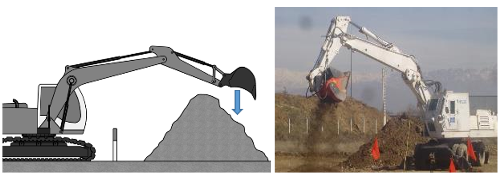
Figure 4 – Excavating material from spoil pile to crush –The HALO Trust
Anything left over in the bucket after crushing may be placed into an inspection area for further inspection.
Stage 3 – Inspection
Once all inspection areas are full, the material can be inspected. For example, by manual deminers using rakes, metal detectors or a simple visual inspection
4.3 Machines and attachments designed to detect hazards
4.3.1 Screening buckets or units
4.3.1.1 General
There are many different types of screening buckets and screening units. They are generally used to screen material to detect items of EO.
The selection of a particular bucket or unit depends on the type of material being screened and the type of EO to be detected.
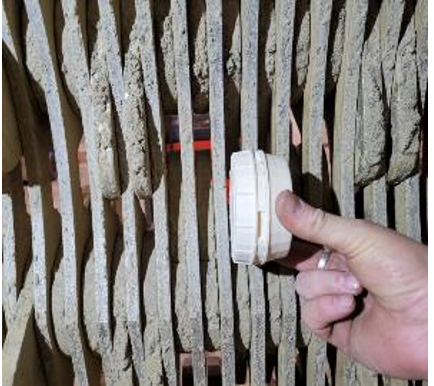
a) Replica PMN-4 AP mine unable to pass through a screening bucket configured to 16 mm spacing
Figures 5 – Examples of EO left over in screening bucket – The HALO Trust
These screening tools have different strengths and weaknesses. For example, some are better at processing wet soil or vegetation and others are better at processing rocky soil or building debris.
4.3.1.2 Screening buckets
Screening buckets come in several sizes and may be attached to different machines, including, but not limited to:
- wheel loaders;
- excavators;
- skid steer loaders; and
- backhoe loaders.
They may be used to excavate the hazardous area (HA) or process a spoil pile. The selection of machine to attach to is determined by factors such as:
- type and size of EO being targeted;
- access to the task area;
- ground conditions on the task; and
- size and weight of the bucket.
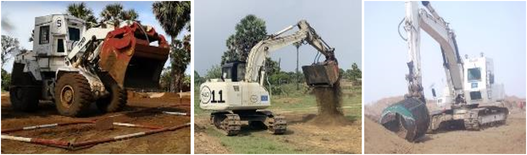
a) Star screening bucket attached to a wheel loader. b) Star screening bucket attached to a tracked excavator. c) Rotary screening bucket attached to a tracked excavator
Figure 6 – Examples of screening buckets attached to different machine types – The HALO Trust
4.3.1.3 Screening units
As with crushing units, screening units are typically loaded with material by another machine. For example, a wheel loader, excavator or backhoe loader.
Additional machinery support may be required to return cleared soil to its original location.
a wheel loader
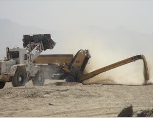
Figure 7 – Examples of screening units loaded by different machines – The HALO Trust
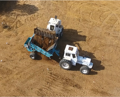
4.3.2 Example of a machine, attachment and process for detecting EO by screening
Machine and attachment
In this example, the machines is a wheel loader (typically 12 t–20 t, although other sizes may be suitable) fitted with a multi-purpose bucket.
NOTE A multi-purpose bucket has a clamp that can open and close – it is sometimes referred to as a 4 in 1 bucket.
A filter that is sized to catch the particular AV mine is fitted inside the bucket.
(4 in 1) bucket from the side
Stage 1 – excavation of soil from the hazardous area
The area may be excavated to a certain depth, collecting soil in the machine’s bucket.
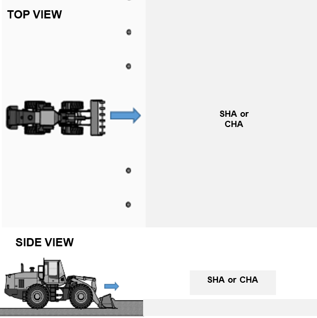
Stage 2 – Transport to inspection area
The machine may then transport the soil to an inspection area.
NOTE This inspection area is often situated close to the HA, to reduce the travelling distance.
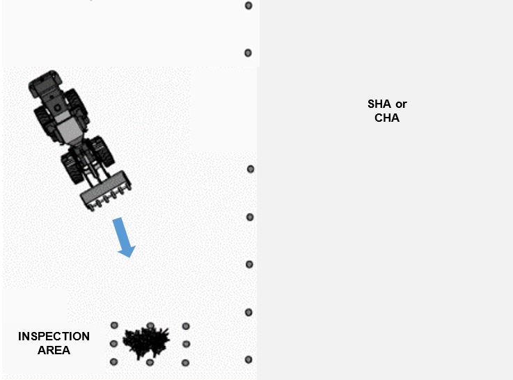
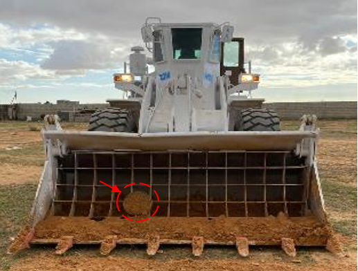
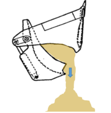
Stage 3 – screening hazardous material
The hazardous soil may then be screened by the bucket by opening and shaking the filter element in a controlled fashion, allowing the soil to fall through.
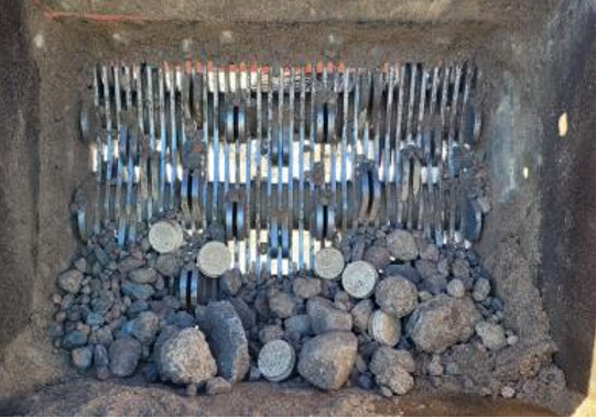
Anything that passes through the bucket is smaller than the filter size. If the filter is correctly sized, larger items such as AV mines remain in the bucket.
Therefore, anything left on top of the filter requires further inspection and, thus, may be placed into an inspection area.
NOTE In this example, AV mines are the EO target. If searching for smaller items like fuzes, AP mines or detonators, these will likely pass through the screening bucket and remain in the processed soil. In this case, the processed soil will also require follow up inspection. For example, by back-blading of the processed soil and then inspection by manual deminers; using metal detectors or rakes.
Stage 4 – Inspection
Once all inspection areas are full, the material in the inspection areas can be inspected, for example, by manual deminers using rakes, metal detectors or a simple visual inspection.
4.3.3 Other common detection methods
Other common detection methods include searching for EO in situ (that is, not through excavation). This may be done through some form of electronic detection or by passing an attachment through the ground to bring EO to the surface; or a combination of these methods on one machine.

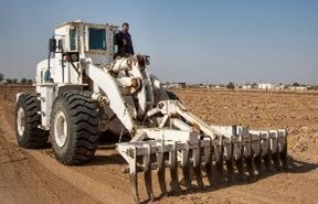
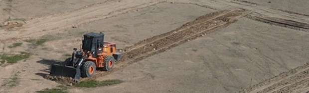
Figure 12 – Technical Survey for improvised explosive devices (IEDs) –
Norwegian Peoples Aid

b) Rotary mine comb (RMC) attached to a tractor – typically used for clearance of minimum metal AV mines
Figure 13 – Clearance of IEDs and AV mines – The HALO Trust
4.4 Machines and attachments designed for ground preparation
4.4.1 Vegetation cutting and tripwire mitigation
Vegetation cutting and tripwire mitigation may be achieved using a directly operated or remote-controlled vegetation cutter.
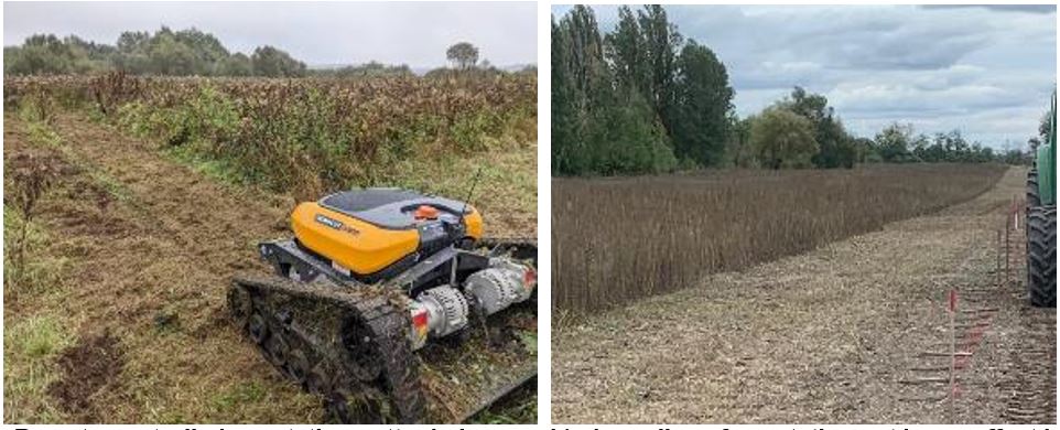
b) Long line of vegetation cut by an offset bush cutter, mounted on a tractor
Figure 14 – Example of vegetation-cutting and tripwire mitigation machines – The HALO Trust
On tasks that have an assessed or confirmed AV mine threat, an attachment like an offset bush cutter may allow for vegetation to be cut without the machine having to enter the hazardous area, and without the attachment putting pressure on the ground.
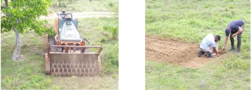
4.4.2 Vegetation cutting, tripwire mitigation and loosening of soil
Machines and attachments may also loosen soil, as well as cut vegetation and mitigate tripwires. In doing so, some EO may be detonated or otherwise destroyed.
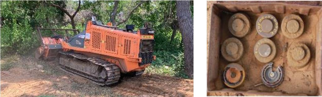
b) Anti-personnel mines found following ground preparation using a tiller attachment
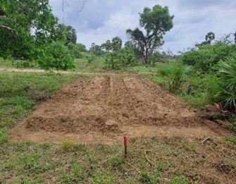
Figure 15 – Example of vegetation cutting, tripwire mitigation and loosening of soil – The HALO Trust
In this type of application, follow up processes should account for:
- items buried by engaging the ground too deep;
- items thrown by the working attachment;
- the levelling effect of the working attachment; and
- the bulking effect created in the aerated soil.
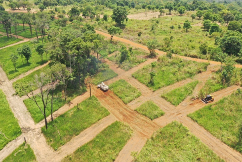
4.4.3 Example of a machine, attachment and process for preparing technical survey lanes on an anti-personnel mine task
The goal of ground preparation is to make follow up demining faster by removing vegetation and loosening soil.
An added benefit may be the inadvertent uncovering of evidence. For example, confirming the location of AP mines, or other EO, as a result of detonations.
Machine and attachment
In this example, the machine is a remote-controlled bespoke demining machine with tiller attachment (~8 t), supported by a directly controlled, armoured, skid steer loader.
NOTE The skid steer is used as a protective shelter for the machine operator.
Stage 1 – Choosing an area to prepare
The distance between TS lanes is selected based on terrain, vegetation and the anticipated EO contamination type, and pattern, in the area.
It is common to conduct TS lanes 25 m or 50 m apart (also referred to as systematic technical survey). It is also good practice to prepare wide enough lanes to allow space for maneuvering and to assist with machine recovery, if needed.
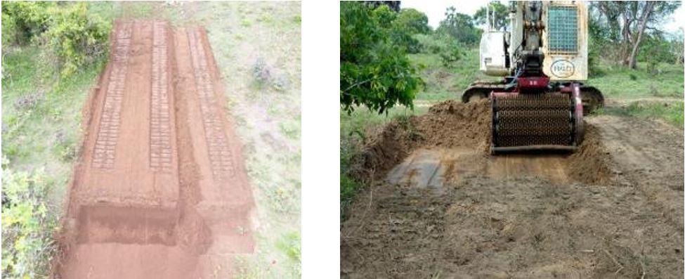
Stage 2 – Choosing settings
The machine and attachment settings used for ground preparation should consider the follow up demining method to be used.
Appropriate machine settings can be determined through onsite testing, conducted in a safe area – this includes measuring and recording of penetration depth.
b) Measuring and recording penetration depth during safe area testing
Figure 16 – Safe area testing – The HALO Trust
There is a risk that items buried deeper by the ground preparation process are missed during follow up. Because of this, the ground preparation process should not be conducted deeper than the follow up method.
Stage 3 – Ground preparation
Once the location of TS lanes, and machine and attachment settings have been selected, ground preparation may be conducted.
Any detonations during ground preparation should be recorded to direct follow up demining toward the area(s) confirmed to contain EO contamination.
Stage 4 – Follow up
After ground preparation has been conducted on the chosen area, the follow up method may be applied. The follow up method(s) need to meet land release requirements.
Animal detection systems or manual deminers are commonly used for follow up. Mechanical excavation and screening or crushing are also possible.
An example of determining the required follow up clearance depth is as follows:
- depth of ground preparation: 15 cm;
- recorded bulking effect: 5 cm;
- levelling effect assumed to be 0 cm because the area is flat;
- minimum depth of follow up clearance: 15 + 5 + 0 = 20 cm
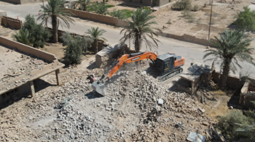
4.4.4 Other common ground preparation methods
Other examples include loosening hard ground and removing rubble to facilitate manual demining.
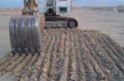
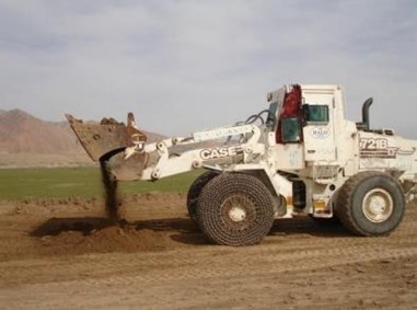
4.5 Other applications
This sub clause provides two examples of support to explosive ordnance disposal (EOD) operations. In both cases, directly operated machines are removing EO (IEDs) from the ground. The location of EO has been previously determined by manual demining teams (marked by red boxes).
In both cases, the use of the machine reduces the requirement for manual approaches to an IED, improving safety.
A rake attachment is fitted to the arm of the backhoe or the front of a wheel loader to engage the ground and lift the IED to the surface.
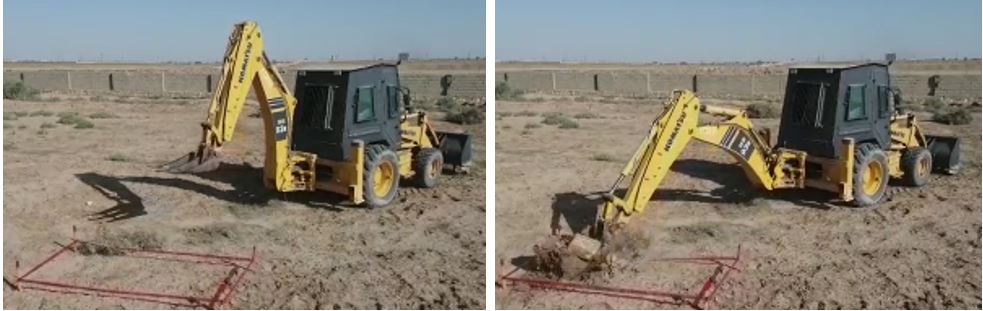
b) IED being lifted from the ground
Figure 21 – Directly controlled machine removing IED from the ground – Mines Advisory Group
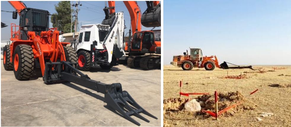
Figure 22 – Wheel loader removing IED from the ground – Norwegian People Aid
Annex A
(normative)
References
[1] IMAS 04.10. Glossary of mine action terms, definitions and abbreviations
[2] IMAS 09.50. Mechanical land release
Amendment record
Management of TNMA amendments
The IMAS series of standards are subject to formal review on a five-yearly basis. However, this does not preclude amendments being made within these five-year periods for reasons of operational safety and efficiency or for editorial purposes.
As amendments are made to this IMAS they are given a number. The date and general details of the amendment shown in the table below. The amendment is also shown on the cover page of the IMAS by the inclusion under the edition date of the phrase “incorporating amendment #.”
As the formal reviews of each IMAS are completed, new editions may be issued. In this case, amendments up to the date of the new edition are incorporated into the new edition and the amendment record table cleared. Recording of amendments then starts again until a further review is carried out.
The most recently amended IMAS are posted on the IMAS website at www.mineactionstandards.org.
| Number | Date | Amendment details |