Warning
This document is current with effect from the date shown on the cover page. As with the International Mine Action Standards (IMAS) these documents are subject to regular review and revision, users should consult the IMAS project website in order to verify its status at (http://www.mineactionstandards.org/, or through the UNMAS website at www.mineaction.org)
Copyright notice
The International Mine Action Standards (IMAS) are owned, controlled and copyrighted by the United Nations. None of the materials provided in IMAS may be used, reproduced or disseminated, in whole or in part, in any form or by any means, without prior written permission from the United Nations acting through the United Nations Mine Action Service (UNMAS), except as set out below. None of the materials in IMAS are to be sold.
The use, reproduction or re-dissemination of IMAS by third parties, in whole or in part, is permitted provided that the United Nations is appropriately attributed and provided also that such use, reproduction or redissemination is not for commercial purposes. The United Nations may be attributed by the placement of the following text: Used and reproduced with permission of the United Nations.
Director
United Nations Mine Action Service (UNMAS)
1 United Nations Plaza New York,
NY 10017
USA
E-mail: mineaction@un.org
Telephone: +1 (212) 963 0691
Website: www.mineactionstandards.org
Foreword
CWA 14747:2003 is now reissued as CWA 14747-1:2003 following the publication of CWA 14747-2:2008.
This CEN Workshop Agreement (CWA) has been drafted and approved by a Workshop of representatives of interested parties on 6 May 2003, the constitution of which was supported by CEN following the public call for participation made on 13 November 2001. The Chairmanship and Technical Secretariat for this CEN Workshop 7 were provided by the European Commission (EC) - Joint Research Centre (JRC) at Ispra (Italy). The professional standardization support was provided by UNI (Italian CEN Member).
The following organisations have given a consistent and active support to the project:
-
International Test and Evaluation Program for Humanitarian Demining (ITEP), based on a mandate issued by the ITEP Board of Directors to EC JRC.
-
United Nations Mine Action Service (UNMAS).
-
Geneva International Centre for Humanitarian Demining (GICHD).
The development of this CWA has benefited from an:
-
EC JRC significant financial support to the process.
-
EC - EuropeAid Co-operation Office, financial contribution allocated in the context of the EC Mandate M/306.
A list of the individuals and organizations which supported the technical consensus represented by the CEN Workshop Agreement is available to purchasers from the CEN Management Centre. These organizations were drawn from the following economic sectors: metal detector manufacturers, R&D institutions with experience of metal detector testing and development, demining engineers and demining Non Governmental Organisations using metal detectors. Participants came from 14 different countries as well as from the European Commission and the United Nations.
The endorsement round for this CWA was started on 9 December 2002 and was successfully closed on 6 May 2003. The final text of this CWA was submitted to CMC for publication on 7 May 2003.
It is to be noted that this CWA represents the current state of the art. However, the contents could be reviewed after one year of implementation in order to input more refined information.
Comments or suggestions from the users of the CWA are welcome and should be addressed to the CEN Management Centre.
This CWA is publicly available as a reference document from the National Members of CEN : AENOR, AFNOR, BSI, COSMT, DIN, DS, ELOT, IBN/BIN, IPQ, IST, MSA, MSZT, NEN, NSAI, NSF, ON, SEE, SIS, SFS, SNV, SUTN, UNI.
Introduction
Metal detectors are an essential part of the toolkit of a humanitarian deminer. Metal detection is one of the few “non-contact” methods available to search for mines in most of the areas of the world where humanitarian mine clearance operations are carried out. Despite the fact that metal detectors have been used for finding mines since the Second World War, there is no universal specification for any performance standards.
Many trials of the capabilities of metal detectors have been performed in recent years, stimulated by the greater international effort to combat the threat posed to civilian populations by mines and unexploded ordnance. However, the lack of an agreed standard for comparing the performance of these instruments has limited the value of this work to the end-users. Without a testing standard, it is difficult to make cross-comparison between instruments to determine which is best-suited to any particular needs.
This CEN Workshop Agreement (CWA) has been prepared by CEN Workshop 7, "Humanitarian Mine Action - Test and Evaluation - Metal Detectors" (CW07). CW07 was established with the objective of developing and agreeing on specifications for the testing and evaluation of metal detectors used in humanitarian mine clearance.
This CWA has been prepared under a mandate given to CEN by the European Commission (EC). In addition, the International Test and Evaluation Program for Humanitarian Demining (ITEP) requested that the Joint Research Centre of the EC initiate this CEN Workshop. Support has also been given by CEN BT/WG 126, by the United Nations Mine Action Service (UNMAS) and by the Geneva International Centre for Humanitarian Demining (GICHD), which is responsible for International Mine Action Standards (IMAS). Close co-operation has been maintained with GICHD and UMAS, with the aim of including it in the IMAS system at a later stage.
CW07 was launched on 8 November 2001 in Brussels, with the approval of the Business Plan. The Workshop process has been chaired by the Joint Research Centre (JRC), which also acted as the Secretariat and financially supported it. Full meetings of the Workshop took place at JRC, Ispra, Italy in December 2001, April 2002 and December 2002. Between the April and December 2002 meetings, a small Drafting Working Group met twice - at DRDC, Suffield in Canada in June 2002 and in Ispra in September 2002 - to make faster progress in writing the CWA.
In formulating the standardized test procedures for this CWA, extensive use has been made of the test procedures developed and followed during the International Pilot Project for Technology Co-operation (IPPTC) for commercial off-the-shelf (COTS) metal detectors [1].
Previous standardization work on demining testing has also been useful in the preparation of this CWA, for example the International Test Operations Procedures (ITOPs) [2], [3], [4]. Other previous work on design of demining test targets has also been useful, for example the MIMEVA project [5].
Tests used in other previous metal detector trials [6], [7], in an existing US military Performance Specification for metal detectors [8] and in a standard for metal detectors used for detection of concealed weapons and contraband in the US penal system [9] were all considered in CW07.
Different parts of the CWA are intended to be used by R&D laboratories, manufacturers, operators of test and evaluation facilities, organizations needing to procure metal detectors, Mine Action Centres and metal detector operators in the field.
The order of the testing followed in this CWA follows a logic that begins with tests of the basic operating performance. These tests are in the most controlled conditions, for which targets are in air not soil. To achieve such controlled conditions requires equipment and facilities that are usually not available in field environments so many of these tests need to be performed by specialized laboratories. Analogous tests are however specified for less-controlled conditions. Next the CWA describes tests on targets in soil – again as controlled as possible. Tests then follow that may be feasibly performed in the field with a minimum of equipment.
Few users of this document will wish to, or be able to perform all of the tests specified. A user in the field under MAC control for example, may perform the detection reliability test, some of the tests of operational performance characteristics and some of the basic in-air and in-soil sensitivity measurements. However, the value of testing is greatly increased if a laboratory has already performed controlled tests, for example to determine whether the sensitivity of the detector under test varies with operating temperature.
Manufacturers form one group of users of this CWA. As well as performing tests according to this document, manufacturers can also help others in their testing by provision of information on their product. CW07 recommendations for the minimum set of information that manufacturers supply to users for help in evaluation are given in Annex C.
Users of this CWA who wish to conduct a trial of various metal detectors using the tests specified, may also wish to conduct a pre-trial assessment to exclude detectors at the beginning that clearly do not meet their requirements. Such a pre-trial assessment would include one or more of the tests specified in the CWA, with acceptance levels set by the users according to their own requirements. The basic in-air sensitivity measurement as specified in 6.4 could be used for example, with a minimum acceptance level for the maximum detection height.
It is planned that the publication of this CEN Workshop Agreement will be supported by training sessions on how to use and implement it and by an extensive experimental verification in which all users are encouraged to participate.
1. Scope
This CWA provides guidelines, principles and procedures for the testing and evaluation of metal detectors.
NOTE This CWA is to be used by manufacturers, test and R&D organizations and field demining groups including Mine Action Centres. It is intended that the users will select the appropriate portions of this document.
This CWA applies to all hand-held types of metal detectors for use in humanitarian demining. The Agreement is intended to be used for "commercial off-the-shelf" (COTS) detectors, but many of the tests specified within it could be applied to instruments under development.
2. Normative References
This CWA incorporates by dated or undated reference, provisions from other publications. These normative references are cited at the appropriate places in the text and the publications are listed hereafter. For dated references, subsequent amendments to or revisions of any of these publications apply to this CWA only when incorporated in it by amendment or revision. For undated references the latest edition of the publication referred to applies. These and other, non-normative references are also given in the Bibliography at the end of the CWA.
IMAS 04.10, Glossary of mine action terms and abbreviations, First Edition, 01 October 2001, UNMAS, New York
IMAS 03.40, Test and evaluation of mine action equipment, Draft First edition, 01 October 2001, UNMAS, New York
IEC 60068-2-27:1987 Basic environmental testing procedures. Part 2: tests – test Ea and guidance: shock IEC 60068-2-29:1987 Basic environmental testing procedures. Part 2: tests – test Eb and guidance: bump
IEC 61000-4-2:1995 + A1:1998 + A2:2000, Electromagnetic compatibility (EMC), Part 4-2: Testing and measurement techniques – Electrostatic discharge immunity test. (=EN 61000-4-2:1995 + A1:1998 + A2:2001)
IEC 61000-4-3:2002, Electromagnetic compatibility (EMC), Part 4-3: Testing and measurement techniques – Radiated, radio-frequency, electromagnetic field immunity test. (=EN 61000-4-3:2002)
IEC 61000-4-8:1993 + A1:2000, Electromagnetic compatibility (EMC), Part 4-8: Testing and measurement techniques – Power frequency magnetic field immunity test. (=EN 61000-4-8:1993 + A1:2001)
EN 61000-6-1:1997, Electromagnetic compatibility (EMC), Part 6-1: Generic standards – Immunity for residential, commercial and light-industrial environments. (IEC 61000-6-1:1997, modified)
3. Terms and definitions
For the purposes of this CWA, the following terms and definitions apply. Definitions follow Draft IMAS 03.40 or IMAS 04.10 or other references if terms are defined therein.
3.1 alarm indication
A signal to warn of the detection of a metal object. The indication can be visual and/or auditory. A positive alarm indication is repeatable under the same conditions and is not intermittent.
NOTE For metal detectors with auto-zero or other functions giving a dynamic mode response, relative motion between target and detector is required to give an alarm indication.
3.2 alarm indicator
The device used to generate the alarm indication, often an acoustic device giving a characteristic sound.
3.3 blind test
A test in which the detector operator does not know details of the location or the depth or nature of the target(s) being sought.
3.4 controlled laboratory tests
Tests performed in conditions where the external factors that may affect a detector are controlled. For example constant or controlled temperature, movement of detector using motorized and even automated scanning mechanisms to ensure control of detector position and sweep speed.
3.5 demining
Activities which lead to the removal of mine and UXO hazards, including clearance.
3.6 detection
The discovery or finding of a metallic object. The operator is made aware of the detection of a metallic object by means of a true alarm indication on an alarm indicator.
3.7 detection halo
The circle around the actual location of a test target, within which an alarm indication is considered a true indication of detection when performing blind detection tests.
3.8 detection reliability
Detection reliability is the degree to which the metal detector is capable of achieving its purpose, which is to have maximum capability for giving true alarm indications without producing false alarm indications.
3.9 dynamic mode
Some detectors use an auto-zero or high-pass filtering mechanism so that unchanging signals do not cause an alarm indication. This is a way of reducing noise signals from magnetic soils, for example. Only changes in signals produce an alarm indication. In this document, this is defined as a dynamic mode of operation.
3.10 electrical conductivity
The ease with which an electrical current flows in a medium. Measured in Siemens per metre (S/m).
3.11 false alarm indication
Alarm indication not caused by the presence of a metal object.
3.12 field tests
Tests to determine the performance of a metal detector in conditions that are close to real operating conditions.
3.13 forward direction
The direction perpendicular to the sweep direction for a metal detector in normal use. Typically the direction in which the operator faces while using the detector.
3.14 ground compensation
An operating function of a metal detector, designed to reduce or eliminate alarm indications from noisy soil while maintaining its detection capability for metal.
3.15 heterogeneous electromagnetic properties
A medium whose electrical conductivity and/or magnetic susceptibility are not the same at all points within the volume of the medium interrogated by a metal detector and therefore whose effect on a metal detector can vary with location is defined as heterogeneous within this document.
3.16 homogeneous electromagnetic properties
A medium whose electrical conductivity and magnetic susceptibility are the same at all points within the volume of the medium interrogated by a metal detector and therefore whose effect on a metal detector does not vary with location is defined as homogenous within this document.
3.17 immunity (to an electromagnetic disturbance)
The ability of a device, equipment or system to perform without degradation in the presence of an electromagnetic disturbance (see [14]).
3.18 in-air tests
Tests to determine the characteristics and performance of a metal detector, without the influence of soil.
3.19 in-soil tests
Tests to determine the characteristics and performance of a metal detector for targets buried in soil .
3.20 less-controlled tests
Tests performed in conditions without the same degree of control over test variables as in controlled laboratory tests. Such tests may be performed indoors without temperature control, or outdoors. The detector may be manipulated manually, but usually with the assistance of jigs and timing devices to control position and sweep speed.
3.21 magnetic susceptibility
The degree to which a medium becomes magnetized in an applied magnetic field. Measured in dimensionless SI units.
3.22 maximum detection height
The maximum height above a test target at which a metal detector at given settings produces a true alarm indication due to that target.
3.23 metal detector
A device which uses the principles of electromagnetic induction to reveal the presence of metal in its vicinity.
3.24 mine
munition designed to be placed under, on or near the ground or other surface area and to be exploded by the presence, proximity or contact of a person or a vehicle.
3.25 noisy soil
Soil that by its composition and/or layering or structure, reduces the performance of metal detectors, to the extent that the operator’s task is made more difficult. This performance reduction is most likely to be a reduced sensitivity to metal and/or producing signals that are not easily distinguished from signals from metal.
3.26 open test (non-blind test)
A test in which the detector operator knows details of the location or the depth or nature of the target(s) being sought.
3.27 realistic test target
A test target designed to simulate the geometry and material properties of mines or of the metal components contained in mines. Realistic targets also include real mines, mines without explosive or otherwise rendered safe.
3.28 sensitivity
The sensitivity of a metal detector is the measure of its capability to detect metal objects. A detector having a high sensitivity can detect small metal objects at a given distance that may be undetected by one having a low sensitivity. The sensitivity of all detectors reduces with distance from the detector sensor head. In many detectors the sensitivity may be adjusted. Within this document, sensitivity is measured in terms of the maximum height of the detector head above a given metal test target at which the target can be detected. Sensitivity may also be expressed as the minimum target (in terms of size, shape and material) that can be detected at a given height above target.
3.29 sensitivity profile (footprint)
The sensitivity profile of a metal detector is a plot of the variation of detection sensitivity with location beneath the detector sensor head along one axis of the sensor head or in two dimensions. The location and extent of the area of maximum sensitivity is of particular interest when specifying the maximum step between detector sweeps to ensure full coverage of an area.
3.30 sensor head
The part of the metal detector (usually a flat coil arrangement) that generates and receives alternating magnetic fields in order to detect metal objects.
3.31 sensor plane
The plane of the detector sensor head (typically a coil) that is kept parallel to the ground in normal operation.
3.32 static mode
Some detectors do not perform auto-zero or high-pass filtering on their output. When an alarm indication is given due to the proximity of a piece of metal, it continues for as long as the metal is there, even if the detector is held motionless. In this document, this is defined as static mode of operation
3.33 soil
The medium in which mines may be buried in the ground
3.34 sweep direction
The direction in which the sensor head of a metal detector is moved over the ground in normal operation. This is typically a side-to-side (transverse) direction in the plane of the sensor head, when the detector is held in its normal position.
3.35 test
Determination of one or more characteristics (of a metal detector) according to a procedure
3.36 test lane
A metal detector test area (usually long and narrow) that mimics the lanes into which minefields are divided for clearance operations.
3.37 test target
An object that is used to test the detection performance of the metal detector. This is a metallic item that can be intended to mimic the response of a mine or mine component, or it can be a simple metal object to be used in sensitivity measurement.
3.38 trial
A series of tests organized in a systematic manner, the results of which lead to an overall evaluation of a component, of equipment or of a system.
3.39 true alarm indication
Alarm indication caused by the presence of a metal object.
3.40 unexploded ordnance (UXO)
Explosive ordnance that has been primed, fuzed, armed or otherwise prepared for use or used. It may have been fired, dropped, launched or projected yet remains unexploded, either through malfunction or design or for any other reason.
4. Symbols and abbreviations
4.1 EMC
Electromagnetic compatibility. Considerations of the emission of electromagnetic fields and radiation from equipment, or the immunity of the equipment to such electromagnetic fields and radiation.
4.2 GICHD
Geneva International Centre for Humanitarian Demining
4.3 COTS
Commercial off-the-shelf. A fully-developed product available on the market. Not a technology demonstrator or prototype
4.4 IMAS
International Mine Action Standard
4.5 ITEP
International Test and Evaluation Program for Humanitarian Demining
4.6 ITOP
International Test Operations Procedure, a testing standard agreed between French, German, UK and US government defence establishments.
4.7 MAC
Mine Action Centre
4.8 NGO
Non-Governmental (non-profit) Organization, such as a charitable aid and development organization
4.9 R&D
Research and development.
5. General testing principles
5.1 Purpose of the specified tests
IMAS 03.40 gives categories of trials in which testing and evaluation of mine action equipment may take place. Of the four categories given, this CWA applies to the "consumer report" and "acceptance trials" categories.
-
A "consumer report" trial aims to test equipment against standard general tests, so that the results are of general interest to metal detector users.
-
An "acceptance trial" aims to test equipment against specific requirements of a customer, in order to make purchasing decisions, for example.
CW07 was established primarily because of a need for standardization in the consumer report category of testing [1]. For example, it is useful to make a general comparison of detection capabilities using standard targets. Many parts of this CWA are also designed be used to test against specific requirements or specific local conditions, which may or may not form part of acceptance trials as defined above. For example, the detection capability of detectors for a particular target of interest can be measured.
The tests of detection capability for targets in air and in soil are designed to provide comparative results of the performance of metal detectors and are conducted under controlled conditions. The influence of various factors, environmental conditions for example, can then be measured. These fundamental tests of detection capability are very useful, even when performed in less-controlled conditions and are used as a reference throughout the CWA.
Tests that are more representative of actual humanitarian demining operations, are often conducted locally in countries of intended use. This means that a metal detector can be tested in conditions similar to those that are likely to be encountered during operation. By their nature, these field tests tend to be less controlled, although appropriate measures are taken in an effort to ensure that the tests specified form a valid basis for comparison of detector performance.
The following table gives a matrix of the tests of the CWA, showing how the tests fit into the different categories above. For example; whether they are appropriate for a consumer report or acceptance trial, whether they are intended as controlled (laboratory) or field tests and whether they are best performed open or blind.
Testing categories:
-
trial type; consumer report trial (CRT) or acceptance trial (AT),
-
open or blind testing
-
test environment; well-controlled laboratory-type (lab) or less-controlled field-like environment (field)
-
Test performed on target in-air (air) or in-soil (soil)
-
in the table means that the test is intended principally for this category
-
in the table means that the test may also be used in this category
-
Key tests are in bold type. These tests should normally be performed as a minimum in a trial.
Table 1 — Categories of testing
| Clause | Test | Testing category - CRT | Testing category - AT | Testing category - Open | Testing category - Blind | Testing category - Lab | Testing category - Field | Testing category - Air | Testing category - Soil |
|---|---|---|---|---|---|---|---|---|---|
| 6 | Detection capability testing in-air | ||||||||
| 6.3.3 & 6.4.1 | General test – Measuring the maximum detection height | ● | ● | ● | ● | ● | ● | ||
| 6.4.2 | Sweep speed – mechanized movement | ● | ○ | ● | ● | ● | |||
| 6.4.3 | Sweep speed – manual movement | ● | ○ | ● | ● | ● | |||
| 6.4.4 | Repeatability of sensitivity on set-up | ● | ○ | ● | ● | ○ | ● | ||
| 6.4.5 | Sensitivity drift | ● | ○ | ● | ● | ○ | ● | ||
| 6.5.2 | Minimum target detection curves for steel balls | ● | ● | ● | ● | ● | ● | ||
| 6.5.3 | Minimum target detection curves for other metals | ● | ○ | ● | ● | ○ | ● | ||
| 6.6 | Detection capability for specific targets | ● | ● | ● | ● | ● | ● | ||
| 6.7.1 | Sensitivity profile (footprint) measurement - Method 1 | ● | ○ | ● | ● | ● | |||
| 6.7.2 | Sensitivity profile (footprint) measurement – Method 2 | ● | ○ | ● | ● | ○ | ● | ||
| 7 | Immunity to environment and operational conditions | ||||||||
| 7.2 | Sensor head orientation and shaft extension | ● | ○ | ● | ● | ○ | ● | ||
| 7.3 | Moisture on sensor head | ● | ○ | ● | ○ | ● | |||
| 7.4 | Temperature extremes | ● | ○ | ● | ● | ○ | ● | ||
| 7.5 | Temperature shock | ● | ○ | ● | ● | ○ | ● | ||
| 7.6 | Sensitivity during battery life | ● | ● | ● | ● | ○ | ● | ||
| 7.7 | Effect of EM/RF interference | ● | ○ | ● | ● | ● | |||
| 8 | Detection capability for targets buried in soil | ||||||||
| 8.2 | Minimum detectable target as a function of depth | ● | ● | ● | ● | ○ | ● | ||
| 8.3 | Detection capability for specific targets in soil | ● | ● | ● | ● | ○ | ● | ||
| 8.4 | Fixed-depth detection test | ● | ● | ● | ○ | ● | ● | ||
| 8.5 | Detection reliability tests | ● | ● | ● | ● | ● | |||
| 8.6 | Additional detection reliability testing | ● | ● | ● | ● | ● | |||
| 9 | Operational performance characteristics | ||||||||
| 9.2 | Target location accuracy | ○ | ● | ● | ○ | ● | ● | ○ | |
| 9.3 | Shape determination of targets | ○ | ● | ● | ○ | ● | ○ | ● | |
| 9.4 | Resolution of adjacent targets | ○ | ● | ● | ○ | ● | ● | ||
| 9.5 | The influence of specific media on detection | ● | ● | ○ | ● | ● | |||
| 9.6 | Detection near large linear metal objects | ○ | ● | ○ | ● | ● | |||
| 9.7 | Effect of specific electromagnetic interference sources | ● | ● | ● | ● | ||||
| 9.8 | Mutual interference between detectors | ○ | ● | ● | ○ | ● | ● | ||
| 10 | Evaluation of ergonomic and operational aspects | ||||||||
| 10.1.1 | Shock and bump tests | ● | ○ | ● | ● | ● | |||
| 10.1.2 | Drop tests | ● | ● | ● | ● | ● | |||
| 10.3 | Interchangeability of parts | ○ | ● | ● | ○ | ● | ● |
5.2 Guidance for field evaluation and assessment
5.2.1 General
Many of the tests specified in this document are intended for use in the evaluation of metal detectors in field tests, for example for selection of detectors prior to procurement. This testing would mainly fit into the "acceptance trial" category as defined by IMAS 03.40.
The results of testing in a laboratory or another field situation, remote from the required clearance site, provide an essential background for the pre-selection of suitable detectors for a particular user to test. The particular local conditions where humanitarian mine clearance is required will however create specific requirements – perhaps more demanding than those in previous trials. Field evaluation and assessment of metal detectors is therefore normally required before any final selection of a metal-detector.
Field evaluation and assessment includes conducting tests that may confirm the results of previous testing that has been done in more controlled environments. However, laboratory testing does not attempt to replicate the many variables and conditions found in demining around the world. As a result, it is the responsibility of the end-user to evaluate the relevance of the results in any particular local conditions. In this way, the field testing may be seen as "confidence testing" but also provides the opportunity to achieve more than that.
Field-tests are intended to:
-
assess detector performance in the potential user's field conditions;
-
provide users with the opportunity to assess ergonomic preferences and ease of actual use;
-
build confidence in the ability of any selected detector to meet the user's performance needs;
-
allow evaluation of the field-relevance of the earlier test results;
-
extend existing knowledge of detection capability for recorded detector/target/soil combinations.
5.2.2 Pre-selection of detectors
When an acceptance trial is to be performed with the aim of selecting the best detector or detectors to meet particular user needs, previous results from laboratory tests and any field evaluations made by other user groups may be used to create a list of the detectors to be tested. The main pre-selection criterion will often be the capability for detection of relevant targets in appropriate conditions (for example, similar soil properties).
5.2.3 Repeatability of field testing
Field assessments are performed to determine how detectors perform in specific local conditions. Nevertheless, these tests need to be done in a common, repeatable way so that the results are useful more generally. Results may be then used by other groups for comparison, or by the same group at a later date. Following the testing and reporting requirements of this document ensures that this comparison is possible.
5.2.4 Content of field testing
The tests to be performed in a trial for field assessment are defined in 5.1, in the "field" column of Table 1. In this table the key tests are also identified that should normally be performed as a minimum in any trial.
5.3 Metal detector performance
The most important characteristic of metal detector performance is the capability for detection of metal objects at distance. The smaller the metal object and the further it is from the detector sensor head, the lower is the probability that the object will be detected. The relationship between the size (and shape, orientation and material) of a metal object and the distance at which it can be detected is therefore used to determine detector performance.
Within this document, detection capability is measured in terms of the maximum height of the detector head above a given metal test target at which the target can be detected. By implication, detection capability may also be expressed as the minimum target (in terms of size, shape and material) that can be detected at a given height above target (and in a given orientation).
Maximizing the detection capability of a detector in order to detect small or distant objects is however not the only consideration for optimizing detection performance in demining. All detectors suffer a certain amount of unwanted noise; for example from external electromagnetic fields, from the electronics of the instrument itself and due to the electromagnetic properties of the soil over which the detector is used. Evaluation of detector performance therefore takes these effects into account, particularly the latter. The capability for detecting metal targets at a controlled depth in soil is the key basis on which comparisons can be made between detectors.
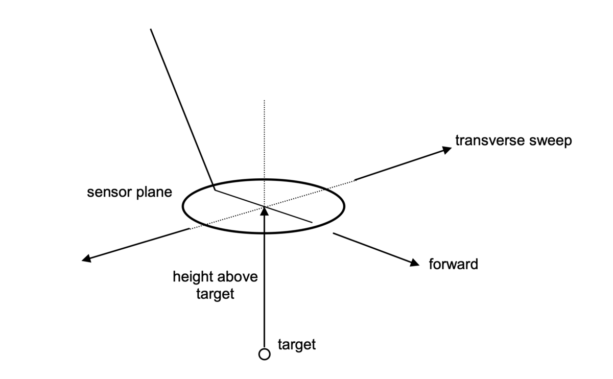
5.4 Test geometry
In the tests specified, the convention for describing the geometric configuration of the detector, target and their relative movement shall be based upon that for a detector in normal field use. The convention shall be that the target be fixed and the detector swept from side to side (transversely) above the target, with the plane of the detector sensor head kept horizontal – parallel to the soil where present. The use of terms in the test specifications shall be understood as applying to this conventional configuration.
If the design of a detector means that its normal mode of use is different to the convention above, the tests shall be changed accordingly. For example if a detector is swept forwards and backwards in normal use, then it shall be used in this way in the tests.
It is possible for some of these tests that it is more convenient to use a different configuration, for example to keep a detector fixed and move a target. Where such different configurations are used they shall be physically equivalent to the conventional configuration. For example, the effect of sweeping a detector sensor head through the earth's magnetic field should be considered.
The height of the sensor head above the target shall be measured between the underside of the sensor head and the top of the target. Figure 1 shows the co-ordinate convention.
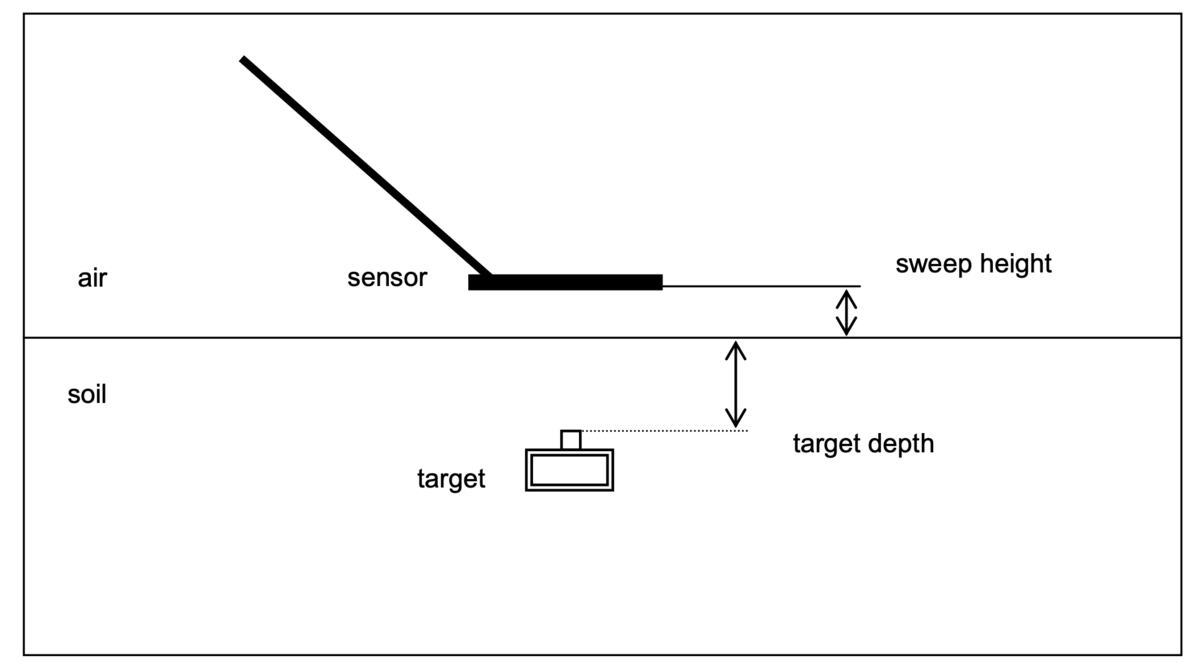
For detection tests in soil, the detector sweep height is measured between the underside of the sensor and the soil level. The target depth is measured between the soil level and the top of the target (see Figure 2). The total height of the sensor above the target is therefore the sweep height plus the target depth. For detection tests in air, the height of the sensor above target is measured directly.
NOTE When comparing tests in soil with those in air, the sweep height above soil shall be taken into account. It is therefore possible for the "equivalent target depth" of a test in air to be negative.
5.5 Criterion for determining detection
This document applies to hand held metal detectors of the types used in humanitarian mine action. Most of these detectors are designed to be easy to use in difficult conditions, by operators without a high level of technical education. The detection of metal is therefore usually indicated by a simple acoustic alarm. In the field it is up to the trained operator to interpret whether the sound he hears is an alarm indication. As this is the actual situation in the field, the tests specified in this document requiring detection of a target are also based on recognition of the alarm by the operator.
Many of the tests specified in this document require the determination of the conditions in which the detector is just detecting a target. At such low signal levels, the alarm indication may well be intermittent. Some judgement is therefore required to determine whether a target has or has not been detected, for example when determining the maximum distance from a target at which detection is possible.
The person performing the tests shall first become familiar with alarm indication for detection of each detector being tested.
The criterion for detection as obtained from the manual or otherwise from the manufacturer shall be used for guidance within the tests specified in this document, insofar as it is consistent with the criterion below.
The criterion for detection shall be that the detector gives a consistent, non-intermittent alarm indication, repeatable under the same conditions and audible to a person with normal hearing (for acoustic alarms).
5.6 Test targets
Most manufacturers provide a metal test target to check the proper functioning of their detector. However the test targets provided are not standardized. Some manufacturers use a metal ball, some a pin, others an aluminium plate. It is well known that the distance at which a metal object can be detected by a metal detector depends on the object’s size, shape, material and orientation - among other parameters. Thus the selection of a suitable common set of targets is very important for the purpose of comparing performances of various detectors and results of tests conducted at different times and by different agencies.
Within this document, test targets are specified for each test. The targets used may include the following categories:
- Simple geometric targets.
-
Targets designed to simulate metal components of mines.
-
Test targets designed to simulate a whole mine (generic or specific).
-
Targets that are metal components of real mines or UXO
-
Targets that are real mines or UXO.
Within this document the most important distinction is between the first type and all the others. The first type are not "realistic" insofar as they are not intended to give a response like that of a mine. Simple geometric shapes can however be used for families of parametric test targets with the same shape but different size. Parametric test targets can be used to measure the minimum detectable target size as a function of detector height above target – larger targets being detected at greater height.
The other types of target may all be used in a common way. The maximum height at which the target is detected can be measured, or it can be recorded whether an alarm indication occurs at a given detector height above target or at a given depth in soil.
The details of targets to be used are found in Annex B.
5.7 Requirements for recording of test results
All relevant data relating to a test shall be recorded. This may include the following, depending on the test being performed:
-
Detector make, model, serial number and operating program (software) version if known.
-
Detector settings (as appropriate).
-
Detector operator.
-
Date, start time and end time of test.
-
Target details, including dimensions, materials and drawings where appropriate.
-
Sweep speed.
-
Maximum in-air detection height.
-
Environmental conditions; temperature, humidity, meteorological conditions (as appropriate)
-
Soil type, condition and properties (see section 8.1.4).
-
Sweep height of sensor head above soil surface.
-
Target burial depths (top of target to soil surface).
6. Detection capability testing in-air
6.1 General principles
The tests described below are to examine the metal detector’s capability to detect metal objects in air and assess how this capability is affected by various parameters reflecting conditions that may be encountered during field use. In a field environment and in particular when using the metal detector over soil, it is difficult or impossible to control all of the variables that may affect a detector. In-air tests may however be conducted in a controlled environment, so the effects of different variables can be separated. While a detector’s ability to detect objects in air does not directly indicate its ability to detect objects buried in the ground, such controlled tests are essential for an objective comparison of performance. In addition, such tests provide information needed to understand a detector’s performance in the field.
The tests described within this section seek to measure the detection capability of the detector under controlled, known conditions. The tests record whether detection is achieved or not in the conditions set. No tests of a statistical nature are made in which detection probabilities are evaluated.
Test procedures are also specified for measuring the way that detection capability varies with height above a target by using sets of similar targets with different size. The curves so produced can be used as a baseline measurement for subsequent in-soil tests. This approach also allows the relative sensitivity to different metals to be measured.
Test procedures are specified for the measurement of the sensitivity profile – the way the detection capability varies with position under the sensor head.
As the maximum detection distance is used to measure detection capability, an operator needs to recognize an alarm indication for this measurement (see 5.5). This principle is maintained throughout the tests.
Tests are described below for the preferred situation of a controlled laboratory environment. Many users without access to such facilities may however wish to perform similar tests in less-controlled conditions, for example without mechanized scanning or temperature control. Many of the tests described in this section also give valuable information in less-controlled and even in field conditions. Simplified in-air tests are therefore described where appropriate.
The tests described in section 9 "Operational performance characteristics" were principally intended for use in field- like environments. However these some of these tests also provide useful information when performed in-air, in a controlled laboratory environment such as that described below.
6.2 Equipment
6.2.1 Equipment for controlled laboratory testing
The laboratory tests require a useable test area within the laboratory with a width and length of at least 1 m. Provision shall be made to allow the detector to be raised to a height of at least 1 m above the floor or ground.
The laboratory structure shall be such that no metal part of the structure is close to the detector sensor head. As a guideline, any such metal should be kept beyond 2 m from the edge of the sensor head, or at least five sensor- head diameters, at any time during testing. A laboratory constructed out of non-conducting material is preferred. If it is not clear whether a metal object is far enough away, a simple test shall be performed to verify that the object does not cause the metal detector to alarm when it is on its most sensitive setting.
When selecting materials with which to build equipment, consideration shall be given to the fact that some insulating materials tend to retain a high static charge, which can interfere with metal detector operation. Tests may be required to verify that the materials used do not cause such problems (see 7.7).
For all except the environmental tests, temperature shall be kept constant (to within ±1,5 °C) between 18 and 25 °C for the duration of each test. The actual temperature shall be recorded. Conditions with condensing humidity shall be avoided.
Environmental tests have conditions specified in the relevant sections (7.4, 7.5). The temperature control of the laboratory used for such tests shall provide a range of temperatures sufficient to meet the specified conditions.
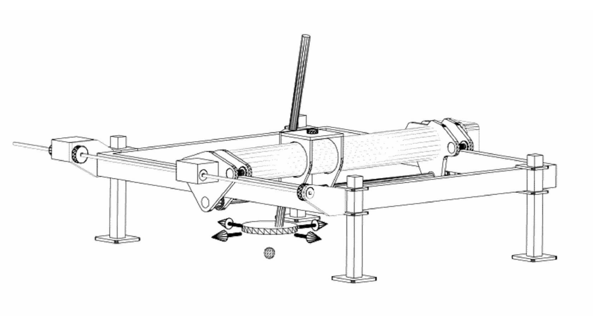
The in-air testing requires that the detector be passed over a variety of targets at various heights and scan rates. For controlled laboratory testing, the detector under test shall be mounted on a mechanical system that provides bi- directional linear or arc scans at least 1 m in length. If arc scans are used, the arc radius shall be at least 1,5 m. It shall be possible to maintain a constant sweep speed (variation within ±10% of speed), adjustable from 0,1 to 1 m/s. Additional capability to conduct two-dimensional scans is necessary to conduct the sensitivity profile scan. A target holder with provision to vary detector height above target easily (in the range of 0 to 1 m) is required. The target holder shall keep the target at least 0,3 m above the floor or ground as some apparently benign flooring materials and soils can influence metal detectors. A example of a suitable scanning device is shown in Figure 3.
The equipment shall have the ability to measure the speed and position of the detector during the movement.
Electric motors or other electrical power devices shall be sited so as to comply with the minimum distances noted above and shall not cause electrical or magnetic interference with the detectors under test. Tests may be required to establish if electrical power devices are interfering with the detector and to determine specific distances that these devices should be removed from the detector.
In one option for the sensitivity profile measurement described in 6.7.1, the (audio) alarm output from the detector shall be recorded together with the horizontal position of the sensor head with respect to the target. Suitable equipment (computer, interfaces and software) is required for this function.
Test targets shall be used from those listed in Annex B. In particular parametric test target sets - metal balls (B.1) and test targets that simulate the metal components of typical mines (B.2) are used.
A spray bottle (approx. 1 litre) with a nozzle to vary droplet size is required to conduct the moisture test.
6.2.2 Equipment for less-controlled testing
For simplified tests, conducted under less controlled conditions, the laboratory mechanized scanner may be replaced by a manual apparatus. The method used shall allow scans to be made that maintain a constant target to detector height. Maximum detection height shall be measurable to the nearest 10mm.
One option is to use a jig that can be used to allow a manual pass of the target over the sensor head. Such a device can be implemented by turning the sensor upside down, propping it up on non-metallic, low static material and laying a piece of wood over the centre of the sensor to allow bridging of the gaps in non-solid heads. The sensor head shall be kept at least 1,5 m from any metal objects other than the test target.
An example of a target holder is a plastic or wooden ruler with double-sided tape fastened to one side to hold the targets at a fixed distance while passing the ruler vertically over the horizontal sensor. The double-sided tape allows easy adjustment of target height.
Larger or heavier targets may require a form of trolley to move the targets smoothly over the sensor head.
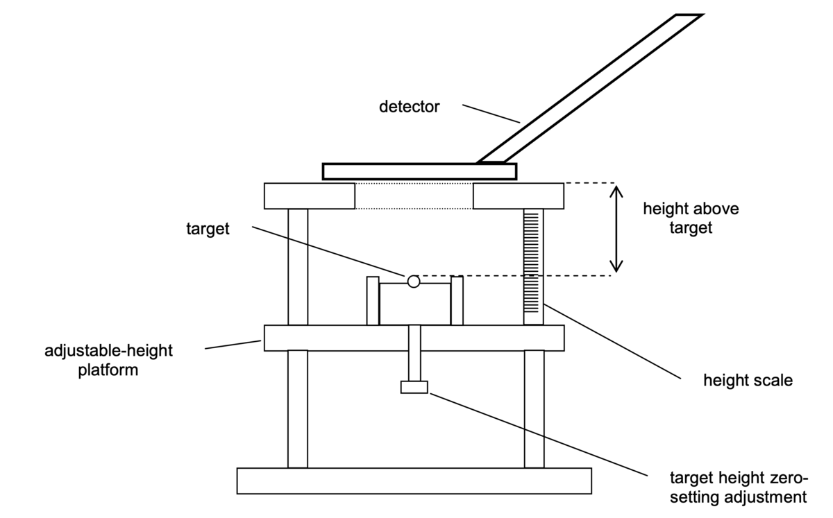
An example is shown in Figure 4 below of a simple non-metallic jig that allows the detector height above the target to be varied – in this case in the conventional configuration of fixed target and moving detector. In this design, the top of each target used can be set to zero before the measurement so that the height above target can be read directly from a scale. The use of such a jig makes manual tests quite well controlled and easily reproducible.
The operator shall attempt to maintain a constant sweep rate for the test. Consistent and known sweep speeds are difficult to produce using this method. However, variations in detector sensitivity due to sweep speed effects can be observed. The use of a metronome or similar device is recommended to help the maintenance of a constant given sweep rate.
When a workplace with a controlled temperature is not available, the temperature at which the test is performed shall be noted. When it is not possible to perform the test indoors, a shaded area away from other activities shall be used where possible.
6.3 General procedures
Detection capability tests in air are based upon the determination of the maximum detection height, from the bottom of the detector sensor head to the top of a target (in the conventional configuration – see Section 5.4), at which a target can be detected.
The detector shall be passed over a target at the constant sweep speed selected. The detector height above the target shall be varied until the maximum height that produces an alarm indication is determined. Section 5.5 defines the criterion that shall be used by the operator to decide what is an alarm indication. Some detectors have a distinctive alarm/no alarm transition within 10 mm while other detectors have a 20 to 30 mm range where it may be difficult to determine whether a detection has occurred or not. A practical increment with which to vary detector height above target is therefore 10 mm. The height increment that shall be used in these tests shall be 10mm or less.
During all tests, the detector operation shall be observed continuously to ensure proper operation, that no electromagnetic interference is occurring due to telecommunications, power transmission etc. and that other objects or the testing process are not causing alarm indications or other difficulties.
In the simplified tests, conducted in less controlled environments, an increased awareness must be given to aspects such as presence of metal, electromagnetic and radio frequency interference sources including but not limited to power lines and transformers, broadcast stations (radio and television) and radar sites.
The detector shall be set up according to the procedure described in the operating manual. The detector shall be used according to the directions given by such manufacturer manual(s). The detector shall be set-up (if applicable) in a suitable mode – the mode in which detection capability is to be measured. The sensitivity and other settings (where applicable) shall be recorded.
A check shall first be conducted using the manufacturer’s test piece (if supplied) to confirm detection at the specified distance to ensure proper operation. This check is only to ensure that the detector is working correctly according to the manufacturer's requirements before testing – for example when the tests are being used to give data on the performance of a particular model of detector.
6.3.1 Preparing and mounting the detector
Batteries of appropriate type and adequate condition shall be installed in the detector. Rechargeable batteries shall have an adequate charge before starting each test. The detector shall not be switched on immediately, as some tests require starting with a “cold” detector.
Fasten the detector on the mechanical scanner (where used) in a manner that allows maximum scan rates without excessive stress on the detector. The cable routing should ensure that it does not catch or snag on any part of the structure and cause undue stress to the cable. This also applies to other detector parts.
The sensor head plane shall be maintained parallel to the scan plane. The sensor head to handle/shaft angle shall not change during the test.
6.3.2 Aligning target and detector
The target to be used shall be selected and placed on the target holder in the correct orientation. Adjust the position of the target and detector sensor head to ensure that the required sweep path is followed and that the sensor height above the target is maintained.
Detectors may have a simple circular single coil in the sensor head or more complex multi-coil and non-circular shapes. The location of maximum sensitivity to a target varies with the design of the sensor head. The detector sensitivity (maximum detection height) shall be measured with the most sensitive part of the sensor passing over the target. Maximum sensitivity may occur at the geometric centre of the sensor, at the sensor edges or other locations depending on the target and the sensor height above target. Therefore, some testing may be required to determine where the appropriate target position should be. Section 6.7 gives details on how to measure the full sensitivity profile or footprint. A simple manual trial at the required height is however sufficient to find the maximum sensitivity location for the purpose of the following tests. It is recommended that manufacturers provide information for the maximum sensitivity location of the sensor.
When target and detector alignment is complete, a specific part of the detector sensor can be scanned over the target in both directions. The sensor height above the target shall be adjustable while keeping the sensor head plane parallel to the scanning plane.
For manual tests, marking the relevant positions on the sensor head may help to maintain correct alignment.
6.3.3 Measuring the maximum detection height
This procedure describes how to measure the maximum detection height for any target.
The detector shall be swept over the target and the sensor height above the target adjusted until an alarm indication is obtained from its detection. Sweep the sensor over the target at least five (5) times to determine whether detection is consistently indicated at this height (Section 5.5). Increase the sensor height above the target in increments (of 10 mm max.) until detection is not consistently indicated for repeated sweeps. The previous position is the maximum detection height. An example test form is given in Annex D.1.
An estimate shall be made of the accuracy to which the maximum detection height can be measured. This estimate shall include the uncertainty arising from judging the detection limit and from making the measurement. Report this accuracy estimate – it is expected to be within ± 10 mm.
Some detector models have a “zero”, “audio reset”, or similar function that may need to be used during the conduct of a test. These functions require only a few seconds to complete and do not normally require a sensitivity confirmation check. If those functions meet these requirements (according to the manufacturer's instructions) and require minimal operator effort, the function shall only be used while the sensor is stationary and not near the target or other metal. Every time that this function is used shall be recorded.
6.4 Stability of detection capability
6.4.1 General
The following tests specify how variation in metal detector performance due to a range of operational and environmental conditions shall be evaluated. In each test, the metal detector detection capability as measured in 6.3.3 above shall be used to quantify this performance.
The target used for these tests shall be a 10 mm-diameter chrome steel ball as specified in Annex B, section B.1.
In order to give data that may be compared with previous trials [1], the sensitivity measurements may also be made using the "ITOP insert M0" - a section of aluminium tube - as specified in B.2.
For each test the following shall be recorded: detector make, model, serial number, date, start time, end time, temperature at which test was made, target, sweep speed, detector set-up procedure, each sensor height above target that was evaluated and target "detected" or "not detected" as appropriate at each height.
Unless otherwise stated, the controlled laboratory tests shall be performed at constant temperature (18 to 25°C) as specified in 6.2.1.
6.4.2 Sweep speed – mechanized movement
The speed at which a detector head is swept over a target may have an effect on the sensitivity as measured by the maximum detection height. The purpose of the sweep speed test is to determine how this sensitivity changes as a function of the speed with which the detector head is swept and to determine the optimum speed for best sensitivity. The sweep speed shall be varied from 0,1 m/s to 1 m/s in 0,1 m/s increments. Consideration shall be given to the acceleration/deceleration needed at each end of the scan so that the sweep speed is as required as it passes over the target, without putting undue stress on the detector.
Set up according to 6.3.1 to 6.3.2 with minimum (0,1 m/s) sweep speed. Turn the detector on and allow a warm up period of 3 minutes or other time as recommended by the manufacturer. Adjust the detector according to the manufacturer’s directions. Do not make further adjustments that will affect the sensitivity of the detector. Obtain the maximum detection height for the test target in accordance with 6.3.3. Increase the sweep speed by 0,1 m/s and repeat the process of determining maximum detection height. Continue until maximum detection height at the sweep speed of 1 m/s has been determined or at least until the maximum acceptable sweep speed has been reached. For detectors that operate in static mode, also measure where possible the maximum detection height with the detector stationary. An example test form is given in Annex D.2.
Any variation in the maximum detection height as sweep speed varies shall be reported using a graph as shown in Figure 5. This figure has two curves showing schematically how static-mode and dynamic mode detectors might be expected to behave. The speed or range of speed at which the detector gives maximum sensitivity shall be determined and recorded. This sweep speed shall be used in the subsequent tests 6.4.4 to 7.7.
6.4.3 Sweep speed – manual movement
The objective of this test is to determine the variation of the detector sensitivity as a function of sweep speed and to determine the optimum sweep speed by manual - or non-mechanized - movement of the detector. There are a number of possible ways in which this can be achieved. Configurations in which the detector is fixed and the target moved over it should be considered, as long as it can be ensured that this is physically equivalent to moving the detector over a target. One method is to suspend the target on a simple pendulum and swing it over an up-turned detector sensor head. The speed of the target can be varied by changing the maximum displacement and/or the length of the pendulum.
Although it is not possible to achieve the accuracy in manual sweeping with an operator that is obtainable by mechanized sweeping, it is possible to vary and control manual sweep rate with the aid of a metronome or other timing device.
The measurement shall be made, recording the method used and reported as specified in 6.4.2 above.
6.4.4 Repeatability of sensitivity on set-up
For consistent results and safety, operators should avoid using detectors whose performance changes significantly each time the detector is adjusted or set up for use. It is expected that detectors where the setting up process is digital and the operator simply pushes a button to get the detector ready for search, consecutive settings should essentially produce the same results. Repeated set-up may be performed while a deminer is working and this test is intended to reveal any lack of repeatability that may occur in such a situation.
The purpose of the repeatability test is to determine the variation of the maximum target detection height in successive pre-use adjustments and procedures. The complexity of these adjustments and procedures may vary from adjusting a single control to adjusting a series of controls and switch selections conducted in a specific order according to the manufacturer manuals and training where provided.
Set up detector according to 6.3.1 to 6.3.2 with the test target, an appropriate sweep speed and target to sensor height. Turn the detector on and allow a warm up period of 3 minutes or other time as recommended by the manufacturer. Adjust the detector according to the manufacturer’s directions. Do not make further adjustments that will affect the sensitivity of the detector. Obtain the maximum detection height in accordance with 6.3.3.
Repeat the set-up procedure and sensitivity measurement. This cycle shall be repeated five times. Record the maximum detection heights measured for the five successive set-up cycles. Report any variation observed and compare it with the variation expected from the accuracy limits of the measurement process.
6.4.5 Sensitivity drift
This test determines how much the detection capability of a detector changes over a period of use. Practically, the results are important because if a detector suffers significantly from such short-term drift, the operator will have to adjust the detector frequently.
The objective of the drift test is to determine the variation of the maximum target detection height over a period of three hours after the pre-use adjustments and procedures have been completed. The detector shall have been turned off for at least three hours prior to starting this test.
Note that in controlled laboratory tests, the objective of this test is to determine drift in the absence of any change in ambient temperature. For less controlled tests, the drift effects are combined with effects due to any changing ambient temperature.
Set up according to 6.3.1 to 6.3.2 with an appropriate target, sweep speed and target to sensor height. Turn the detector on and allow a warm up period of 3 minutes or other time as recommended by the manufacturer. Adjust the detector according to the manufacturer’s directions. Do not make further adjustments that will affect the sensitivity of the detector. Obtain the maximum detection height in accordance with 6.3.3.
The process of determining maximum detection height shall be repeated continuously, or at least as frequently as every three minutes, for thirty minutes and subsequently every 10 minutes for a total elapsed time of 3 hours. To determine the maximum detection height at each prescribed time interval, each individual measurement process may need to be started early. The sweep rate and number of consecutive detections will be the main factors to determine how soon before the required time to start each measurement.
6.5 Minimum detectable target as a function of height
6.5.1 Objectives
The way that a signal response produced by a target varies with detector height above the target is different for different detectors, depending on detector coil size and configuration. It is therefore better to characterize a detector's sensitivity at a range of heights, rather than use a single maximum detection height with a single target as a sensitivity measure.
The objective of this test is to measure the detection capability of a detector as it varies with height above a target. The variation of maximum detection height with target size is therefore determined. To do this, a set of parametric targets (of different sizes but the same shape and material) is used for which a sensitivity curve of maximum detection distance versus target size is produced. Thus the detection capability at a given height can be quantified in terms of a minimum detected target size.
Producing the minimum-target detection curves for different materials with the same target shape allows a comparison to be made of the relative sensitivity of a detector to different materials.
6.5.2 Minimum target detection curves for steel balls
The targets used shall be the chrome steel balls as specified in B.1.
To create the detection curve, at least eight (8) balls shall be used, covering the diameter range from 4 mm to 15 mm. The minimum set is:
4 mm, 5 mm, 6 mm, 7 mm, 8 mm, 9 mm, 10 mm and 15 mm diameter.
If the maximum detection distances measured with these balls do not span the maximum required detection distance for the user's application, then the target set shall be extended with larger or smaller balls as necessary using other balls as specified by Annex B.1. Balls with diameters between those specified may also be used in addition.
Successive scans shall be made at optimum sweep speed and the maximum detection height determined according to 6.3.3. An example test form is given in Annex D.3.
The data are collected as maximum height as a function of ball size. However the results shall be plotted on a graph with the maximum detection height on the horizontal (x) axis and the ball diameter on the vertical (y) axis. A best-fit curve shall be plotted joining the points on this graph.
The fitted curve defines the detection capability at any height above target, in terms of the minimum detectable metal ball at that height. A curve with the form of that shown in the Figure 6 below is expected. The estimated uncertainty in the measurement of the maximum detection height is shown here with horizontal error bars.
From this curve the detection capability at 100 mm is defined by a minimum detectable chrome steel ball target of approximately 6,5 mm diameter.
6.5.3 Minimum target detection curves for other metals
The targets used shall be the metal balls as specified in B.1.
For each metal, a minimum of four (4) ball diameters spanning the range of interest shall be used for this comparative measurement of detection capability. Where possible, ball diameters approximately equal to those of the chrome steel balls used in 6.5.2 should be used.
The ball diameter vs. maximum detection height shall be plotted as in 6.5.2 for the balls used and a curve fitted to the points.
The graph is expected to have the form shown in the Figure 7 below, where detection-capability curves for balls of three different metals are shown. For the sake of clarity, the data points have been omitted from this figure.
6.6 Detection capability for specific targets
The objective of this procedure is to determine the maximum detection height in air of any given target for the metal detector and sensitivity setting being used. Such targets may include standard realistic targets (Annex B) mine simulants or surrogates or real mines. At a given setting this makes it possible to rank targets in order of ease of detection for that instrument. The sensitivity characteristics can often be changed by user-adjustable settings on the metal detector. The instrument settings and set-up procedure used for this test shall therefore be recorded.
For many detectors the maximum-sensitivity instrument setting obtainable in-air is not obtainable above certain soils without giving a constant alarm indication. The instrument setting has to be changed therefore, often reducing the sensitivity. Ideally, the target characterization should be performed at a typical setting used for mine detection activities. Unless the sensitivity characteristics at another specified setting are required, the metal detector shall be set up for this test according to the operation manual, to give the maximum in-air sensitivity.
The maximum detection height shall be determined for each of the targets according to 6.3.3.
To measure the detection capability of the detector for different types of realistic target, the maximum detection height for each of the "ITOP" test targets [11] specified in B.2 shall be measured.
NOTE Do not make performance comparisons between detectors on the basis of their response to such targets in air alone, as soils affect some detectors more than others.
6.7 Sensitivity profile (footprint) measurement
The response of a detector depends not only on the height above the target, but also the target’s location on a plane parallel to the detector sensor head. In other words, whether or not a target is detected can depend on what part of the search head is swept over it. It is very important to characterize this aspect of sensitivity variation in order to assess the field performance of a detector. This data can be used to define the overlap needed between consecutive scans to ensure complete coverage at the required sensitivity. If a detector is capable of detecting the targets being sought at the clearance depth only when the target is directly under the central part of the sensor head, then the detector sweeps need to be highly overlapping.
The objective of this test is to determine the sensitivity profile of a detector. The sensitivity profile is the variation of sensitivity with location in a plane parallel to the sensor head. The size and shape of this profile is dependent not only on the detector but also on the target used to measure it; its size, orientation and sensor height above the target.
Two methods are given for this test. The first requires a method of recording and displaying the alarm indication signal graphically and gives the sensitivity profile as a two-dimensional plan. The second method maintains the principle of using the maximum detection distance alone as the measure of sensitivity. This second method gives the maximum detection distance when the detector is swept from side to side with the target under different parts (from front to back) of the sensor head. This method therefore gives the sensitivity profile in one dimension.
6.7.1 Method 1
Set up the detector according to 6.3.1 and 6.3.2 using the target defined in 6.4 and optimum sweep speed. In addition, the scanner shall be set up for a 1 m 1 m square area scan with a 10 mm forward step between each transverse sweep over the target. Ensure that the target is at the middle of the area scanned by the sensor head.
Determine the maximum detection height as in section 6.3.3. The area scan shall be conducted at a minimum of three sensor heights above the target: at 20 mm from the sensor head, at 20 mm closer than the maximum detection height, and at a position half-way between those two heights. Select the first target distance.
Start the data acquisition to record the alarm indication (audio) signal and sensor position. Begin the detector area scan at one corner of the scan area. The resulting data can be displayed as false colour or grey-scale plots (or similar) showing the alarm signal strength vs. target position for each sensor height above the target. Figure 8 below shows this way of presenting the data. From these data the location and extent of the maximum sensitivity regions at each height can be determined. For example, the Figure shows that close to the sensor head, the most sensitive region forms a ring following the coil windings, whereas at a greater height, the centre is the most sensitive location.
6.7.2 Method 2
Figure 8 — Sensitivity profile measurement according to Method 1
This method does not require an area scan positioning system. The sensitivity profile is built up from a series of single sweeps in the normal detector sweep direction as performed in 6.5. On each sweep the maximum detection height is determined for the target used. The sensitivity profile is therefore given in the fore-and aft direction of the detector.
The aim of this test is to plot the sensitivity profile for three targets, chosen in such a way that the variation of sensitivity is plotted close to the detector sensor head, distant from the sensor head and at an intermediate height. Three chrome steel ball targets shall be used for this test, taken from the parametric test target set (B.1). The sizes of ball used shall be chosen as follows:
-
A ball shall be used whose maximum detection height as measured according to section 6.5 is approximately 20 mm.
-
A ball shall be used whose maximum detection height as measured according to Section 6.5 is approximately 150 mm.
-
A 20 mm diameter ball shall be used.
For each target, the sweep series shall start with the target 0,5 m in front of the centre of the sensor head (perpendicular to the sweep direction). The detector shall be swept transversely over the target and the maximum detection distance obtained in accordance with 6.3.3 for the first sweep (if detectable). The relative target-detector horizontal position shall be changed in steps of 10 mm and a maximum detection height determined with transverse sweeping at each step, building up a profile of maximum detection height with position. The final scan line shall be with the target 0,5 m behind the detector. The maximum detection distance is determined irrespective of where in the sweep gives the greatest sensitivity. As the sensor head moves from side to side, the maximum detection height may be under the coil windings for the small target and in the centre for the larger target. An example test form is given in Annex D.4.
A sensitivity profile of the sensor head perpendicular to the sweep direction shall be plotted from the maximum detection distances for each scan. Figure 9 below shows how the sensitivity profile is produced. Part a of the figure shows how the profile is built up with successive transverse sweeps. On each sweep, for each of the three targets, a maximum detection height is measured. Part b of the figure shows a graphical presentation of the profile. The horizontal axis is the position along the detector at which the transverse sweep is made. The vertical axis is the maximum detection height measured on each sweep.
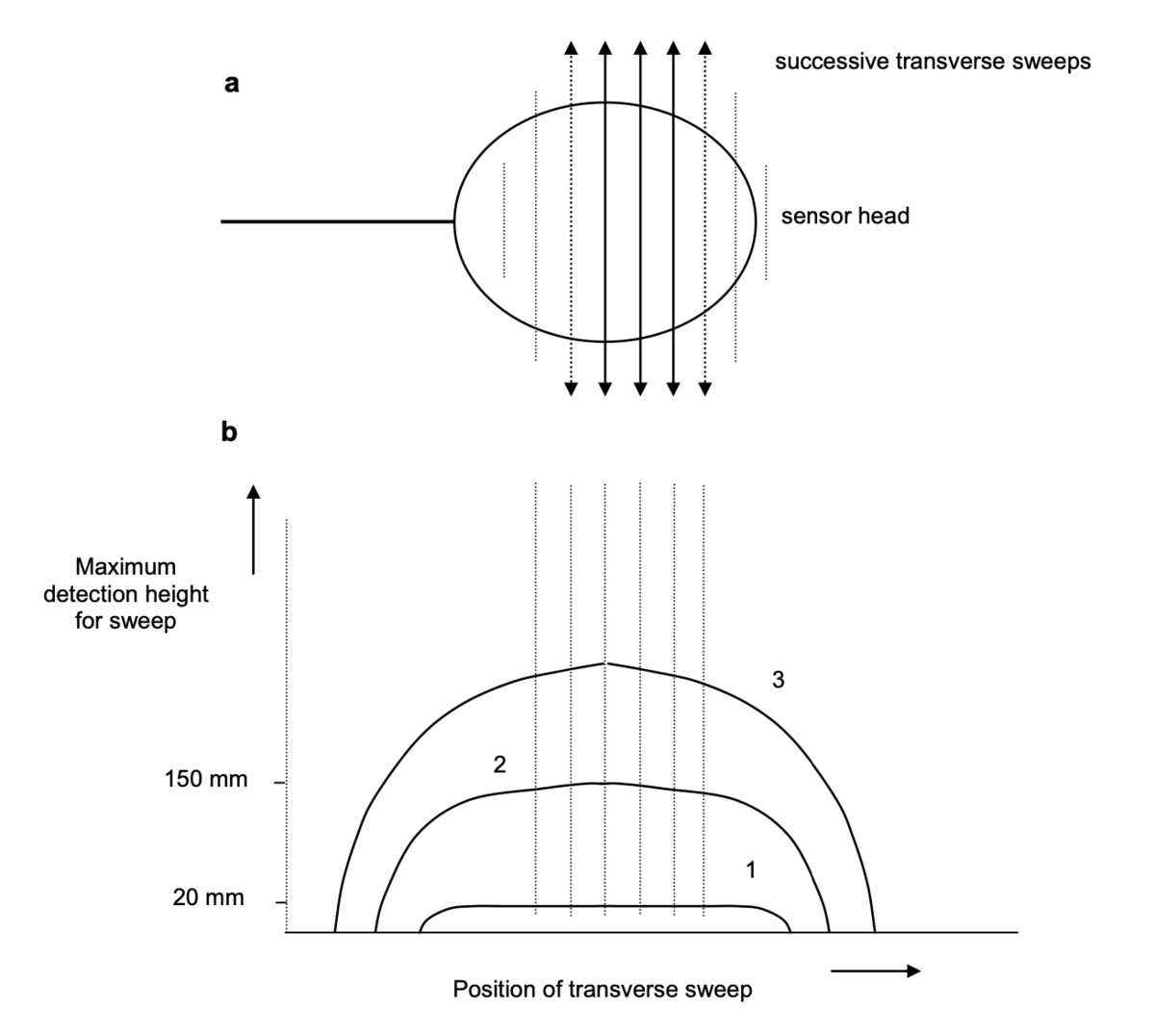
The sensitivity profile can be used to determine the extent of the area under the sensor head that gives a certain detection capability. The advantage of Method 2 is that the detection capability is quantified in the same way as it is in section 6.5.
7. Immunity to environment and operational conditions
7.1 General
7.1.1 Testing principle
The tests in this section are performed following the testing principles of 6.3 and 6.4. Each of the tests determines whether the in-air detection capability is changed by external influences.
7.1.2 Testing procedure
In each of the tests, the effect of adverse conditions on the detection capability is measured according to 6.4.1. An example test form is given in Annex D.1.
7.1.3 Test results and reporting
The detection capability shall be recorded and any change due to the conditions noted.
7.2 Sensor head orientation and shaft extension
The alarm on some detectors can be triggered if the orientation of the sensor head to the shaft is changed during operation, or the shaft length is changed. This test is to determine whether the detection capability of the detector remains the same in these different configurations.
Detectors are usually used either with the operator standing, squatting, or with the operator lying prone on the ground. In the first case, the detector is generally used with the head at an angle to the shaft between 90° and 150°, depending on the task and the height of the operator. In the last case the head is usually in line with the shaft, either fully opened out, or folded back against the shaft. The shaft length used also depends on the operator and the way in which the detector is being used.
The detection capability of the detector shall be measured in the configurations used in operation. The different detector designs and the many ways in which the shaft length and sensor head orientation can be adjusted make it impractical to define all possible configurations in which to test. The configurations tested should however include; the angle and length used for normal standing manual operation and the angle(s) and length(s) used in prone operation. In addition, if performing mechanized scanning, it may be useful to check the detection capability with the sensor head at 90° to the shaft, since this may be the easiest way to mount the detector in the scanning mechanism.
For each of the head-angle and shaft-length configurations to be tested, the maximum detection height above target shall be measured as described in 6.3.3.
7.3 Moisture on sensor head
The purpose of this test is to determine the extent to which moisture on the sensor head affects the detection capability of a detector. When a detector is used in terrain where there is wet grass or other vegetation, the sensor head can get covered in small drops of water. These conditions have been known to cause alarm indications on some detectors.
The moisture test consists of measuring the maximum detection height as an increasing amount of water is sprayed (in the form of a mist of tiny droplets of water) on the search head. The amount of water is controlled such that the range of wetness (from dry to completely wet) is achieved in steps. Due to the time taken to complete a moisture test (typically 20-30 minutes) the results from this test may include some effects of drift that are difficult to separate. However, if a detector is found to have a much larger variation in the moisture test than in the drift test, the effect of moisture can be inferred.
Set up according to 6.3.1 to 6.3.2 with an appropriate target, sweep speed and target to sensor height. Turn the detector on and allow a warm up period of 3 minutes or other time as recommended by the manufacturer. Adjust the detector according to the manufacturer’s directions. Do not make further adjustments that will affect the sensitivity of the detector. Obtain the maximum detection height in accordance with 6.3.3.
Using the spray bottle, a fine mist of clean water shall be sprayed on the sensor head and the maximum detection height measurement repeated. This shall be repeated for five levels of moisture on the sensor head; the first giving a light covering of distinct droplets on the surface and the last providing a maximum amount of water on the search head (so that if more is added, it simply runs off). If the water droplets cause the detector to give an alarm away from the target, this shall be recorded. The sensitivity shall then be reduced or other adjustment made (where applicable - according to the detector) until there is no alarm away from the target. The measurement of maximum height shall then be repeated.
7.4 Temperature extremes
The objective of this test is to determine the variation of the maximum detection height for a range of temperatures. The detector shall be tested in controlled temperatures of 0°C, 20°C and 60°C. The humidity level shall be less than condensing and shall be recorded.
Adjust the temperature in the laboratory to 0°C. Place the detectors under test in the laboratory for at least three- hours immediately prior to testing, so that they reach the laboratory temperature. Make the sensitivity drift test (6.4.5) and then the repeatability test (6.4.4) at the controlled temperature.
This test process shall be repeated at 20°C and at 60°C. 60°C is difficult to obtain in normal laboratory environments. If it is not possible to perform the test using a climatic chamber, it may be useful to do the tests in a sauna for example. If so, be aware of the proximity of metal (e.g. pipes) and interference sources such as electrical heaters.
Record the maximum detection heights for each temperature.
A version of this test without temperature control is possible, simply by taking advantage of extremes of ambient temperature, either indoors or outdoors. In such a case the temperatures for the test shall be recorded.
7.5 Temperature shock
Detectors may be subject to rapid temperature changes such as when taken out of overnight storage at the beginning of the day, significant temperature change over the working day due to solar heat loading and the related effects of partial cloud cover interfering with local sunshine.
The objective of this test is to measure any change in maximum detection height that may occur due to such changes. The test is to conduct the drift test under conditions of a rapid temperature change and will provide indications of how the detector will perform under these conditions and how often the detector will require readjustment. The laboratory room temperature shall be 25°C.
Place the detectors in storage at 0°C for at least three hours immediately prior to testing. Remove the detector from storage and within 15 minutes prepare the detector for testing according to 6.3.1 and 6.3.2. Conduct the drift test 6.4.5 without delay.
Record the maximum detection heights measured over the period of the drift test.
A version of this test without temperature control is possible, simply by taking advantage of differences of ambient temperature, for example between storage outdoors in winter temperatures and indoor operation. In such a case the temperatures for the test shall be recorded.
7.6 Sensitivity during battery life
The purpose of the battery test is to determine whether detector sensitivity changes as the battery is discharged during operation, but before any low-battery alarm is triggered or the detector ceases to function. This test also gives the continuous operating life possible with the batteries used. New unused (or otherwise specified) batteries are installed in the detector and it is switched on and prepared for the test according to 6.3.1 and 6.3.2. The detector shall be left on for the duration of the test.
The maximum detection height shall be measured according to 6.3.3 at regular intervals not exceeding half an hour for the whole test period. Note that ambient temperature may have an effect on battery drain from the detector. The test may be repeated for batteries of different types, ages, and ambient temperatures as required.
Record the maximum detection height over the operating life of the battery. Note whether there is any change in the maximum detection height during the test beyond that due to the accuracy limits of the measurement. Record the total continuous operating time until the detector shows a low-battery indication or ceases to work.
7.7 Effect of EM/RF interference
Metal detectors produce and detect oscillating magnetic fields in order to detect metal in their vicinity. As such they are bound to emit a certain amount of electromagnetic energy and are likely to be affected to some degree by the electromagnetic environment in which they are used. It is important that metal detectors are affected as little as possible by external sources of electromagnetic (including radio frequency) interference that may be encountered at the demining location. It is possible to create simple tests to determine the effect of any one potential interference source. Such specific tests are given in Section 9.7.
If required, more controlled tests shall be made according to the following standards for tests of the immunity of equipment to various sources of potential interference.
-
tests to check that equipment works after electrostatic discharge, according to IEC 61000-4-2:1995 + A1:1998 + A2:2000;
-
tests to check that equipment works when subject to RF radiation, according to IEC 61000-4-3:2002;
-
tests to check that equipment works when subject to power frequency magnetic fields (motors, power lines etc.), according to IEC 61000-4-8:1993 + A1:2000;
-
generic testing standard that applies if there is nothing more specific, according to EN 61000-6-1:2001;
Where tests to determine the immunity of the detector to electromagnetic interference are made, the criterion for immunity used in addition to those specified above shall be the detector's sensitivity. The sensitivity shall be measured by the maximum detection height (6.3.3) as in the other tests in this section, during or after the test as appropriate.
8. Detection capability for targets buried in soil
8.1 General
8.1.1 Principle
In demining operations metal detectors are used mostly for the detection of buried mines. The soil in which the mines are buried will in general hamper the detection performance of the detector.
The objectives of the tests described in this chapter are to determine the degree to which a soil degrades the detection capability of a metal detector and to make evaluations of the detection reliability with buried targets. Many metal detectors incorporate ground compensation functions designed to reduce or eliminate effects of soils. One aim of these tests is to evaluate the effectiveness of such functions.
Some of the test procedures described in this chapter can be regarded principally as laboratory tests in which all relevant parameters are well-controlled. For instance, the tests require the use of one or more dedicated test areas. These test procedures are intended mainly for R&D laboratories, T&E agencies and manufacturers that possess test areas for metal detector tests. As for the in-air tests however, it is possible to perform equivalent tests in less- controlled conditions. For example, manipulation of the detector may be manual rather than mechanized.
Other tests are more appropriate for use in an in-field situation, where conditions are close to those experienced in local demining operations. It is less easy to achieve well-controlled conditions in such a situation. The idea of detection reliability tests is to make an evaluation of the way environmental and operational factors degrade the detection capability - as measured in simple controlled tests.
8.1.2 Equipment and test areas
For the tests described in this chapter, soil test areas are required with a width and length of at least 1 m and a depth of at least 0,5 m. The test areas shall be constructed out of non-conducting material. The presence of metal objects around, above and under the test areas shall be avoided as far as possible. As guidance, the presence of metallic objects should not be allowed closer than 2 m, or at least 5 sensor head diameters, to the test area during the tests. If it is not clear whether a metal object is far enough away, a simple test shall be performed to verify that the object does not cause the metal detector to alarm when it is on its most sensitive setting.
Provisions should be made against leaking of ground water in regions where the ground water level is higher than the depth of the test area. Such a provision can be the presence of a waterproof plastic coating on the sides and bottom of the test areas or a drainage system.
The soil shall be free of all metal objects (other than the targets) that are not part of the normal soil composition. Small pieces of iron that have been buried for long periods might become calcified and look like any other pebble or small rock. These are not be considered as normal soil and shall be removed.
For each soil type present in the test area(s) a plot of at least 1 m 1 m shall be designated for, among other things, detector set-up and calibration purposes. These plots shall be free of test targets or any other metallic object.
During test periods, attention shall be given to the possibility of interference at the location of the test area(s) from electromagnetic fields causing alarm signals. The area(s) free of metallic objects, mentioned above, may be used for verifying the absence of interference, if it is suspected. A test to measure whether a particular suspected interference source is affecting the detector is given in 9.7.
8.1.3 Moving the detector
The detector shall be moved over the test area either using controlled positioning equipment, as described in 6.2 or with manual sweeping. The means used shall be such that the detector under test can be moved over the (buried) target(s) with the plane of the detector head parallel to the soil surface. The detector shall be moveable in the directions (back and forth) that are used during normal sweep operation. It is preferred that the positioning equipment can move the detector back and forth repeatedly along the same line over a distance of 1 m.
Make sure that neither the positioning equipment structure nor its driving mechanisms, such as electric motors, cause interference with the metal detector under test.
Where mechanized scanning equipment is not available, the tests in this section are performed by manual operation of the detector. The positioning, speed and orientation of the detector shall be controlled as closely as possible with the help of suitable non-metallic jigs and timing devices.
8.1.4 Soil types
To measure the effect of soils on the detection capability of metal detectors, the relevant properties of the soils used in the test areas for in-soil tests should be well-known, well-controlled and recorded. According to the current understanding of the influence of the soil on the metal detector performance, the most important soil properties in this respect are the electrical conductivity and the magnetic susceptibility. A property of secondary importance may be the moisture content of the soil, since the moisture can influence the electrical conductivity.
Where possible the magnetic susceptibility and the electrical conductivity of the soil(s) in the test area(s) shall be measured in situ with calibrated measurement instruments, together with the moisture content in the top layer of the soil, ie. to a depth of 0,2 m. The measurement instruments used shall be reported (brand, type and settings, if applicable). These measurements shall be made at a number of locations on the test area(s) (at least one measurement in every 0,25 m2 of the test area). Spatial variations shall be reported. The measurements shall be repeated after any occurrence that may change the soil properties, e.g. rain. The magnetic susceptibility shall be given in dimensionless SI units, the electrical conductivity in S/m and the moisture content as a percentage by volume together with the depth of the measurement(s). A simple classification of soils by their magnetic susceptibility is given in Annex A.3.
NOTE Magnetic susceptibility of soils is a complex (frequency-dependent) quantity and cannot be described fully by a single number, as indicated. It is this fact that causes soil noise effects in many metal detectors. See Annex A.
To determine the capability of a metal detector to cope with noisy soil, tests on soil classified as "severe" in A.3 shall be made.
When no suitable measurement equipment is available, a description of the soil shall be given. Such a description shall contain information on the colour of the soil, its structure in dry and moist state and its grain composition. The description can also contain a comparison with other, more common soil types. Any relevant information on the soil chemical content shall be recorded.
8.1.5 General testing procedure
The detector under test shall be used according to the directions given by the manufacturer in the manual. Initially the detector shall be set up according to the procedure as described in the manual. A plot of soil in the test area, free from metallic objects and at least 1 m 1 m, shall be used for the set-up. The detector shall be configured for the maximum possible sensitivity attainable without giving alarm indications from the soil alone when swept over the soil and parallel to the soil surface at a height varying between 0 mm (contact) and 30 mm. The detector sensitivity setting and other settings (if applicable) shall be recorded.
The in-air detection capability of the detector as adjusted shall be measured according to 6.4.
NOTE This in-air measurement is not intended to give a detection capability in the soil being used. It is merely to record the state of the detector as used for the tests.
It shall be possible to set up the detector for the soil on which the tests are to be performed as described above. It shall be set up so as to give no alarm indications when placed on the soil surface and then brought to a height of 30 mm above the surface. If not, the detector shall not be used on that soil for the tests described in this chapter.
During the detection tests, the alarm assessment of the detector under test shall be made by the operator according to Section 5.5.
8.2 Minimum detectable target as a function of depth
8.2.1 Principle
The aim of this test is to determine the detection capability of the metal detector using buried targets. Detection capability is measured by determining the maximum detection height as in the in-air tests in Section 6. For in-soil tests however, part of the sensor height above target is in soil. This test measures how the detection capability varies with depth in the soil being used.
This test can be used for two different purposes. Information on the detection capability of the detector for these balls buried in well-characterized soil types is useful for the comparison of detectors tested by different manufacturers, laboratories and T&E agencies in "consumer report" trials.
The detection capability in a particular soil can be measured and this information used to evaluate whether a detector is able to meet specific requirements, such as for "acceptance trials".
8.2.2 Equipment and test area
The requirements for the soil test area are defined in 8.1.2 above.
Standard chrome steel ball test targets as specified in Annex B.1 shall be used to measure the detection capability of metal detectors in soils. As a minimum, the following steel ball test targets shall be used: 4 mm, 5 mm, 6 mm, 7 mm, 8 mm, 9 mm, 10 mm and 15 mm diameter, as used in 6.5.
If the maximum detection depths measured with these balls do not span the maximum required detection depth for the user's application, then the target set shall be extended with smaller or larger balls as necessary using other chrome steel balls as specified by Annex B.1. Balls with diameters between those specified may also be used in addition.
The targets shall be placed in the soil in such a way that the depth of the target beneath the surface of the soil is adjustable. To this end, a device shall be used constructed from non-conductive, non-magnetic materials.
One possibility is a rod or dowel on which the target ball is fixed. Such a dowel may have an adjustable length, or a set of such dowels with different lengths may be used. Another possibility for such a device is a plastic tube placed in the soil so that the target can be positioned within the tube. In this case the target ball shall be mounted to a spacer so that the depth of burial can be determined from the length of the spacer that is in the tube.
The overall diameter of the rod, dowel or tube shall be as small as possible, in order to minimize the possibility of the metal detector being affected by what would be an effective void when used in a magnetic soil. It shall be checked that the positioning device does not give a signal with the detector under test.
8.2.3 Procedure
The detector shall be set up according to the general procedure (8.1.5 above). If applicable, the settings used shall be recorded.
Initially the detector shall be swept over the intended target positions with no targets present, i.e. over the empty target positioning device, to verify that there is no alarm from the soil, the positioning device or targets present unintentionally. These sweeps shall be made at the minimum sweep height that is possible (even with intermittent contact with the soil, as long as this does not cause any problems for mechanical scanners). The sweep speed shall be within the optimum range determined for the detector under test in in-air tests (6.4.2 and 6.4.3), or as specified in the manual.
The detector shall be swept at optimum speed over the target positioning device for each different ball diameter in turn. The detector shall be swept at a height of 30 mm above the soil as defined in Annex B.5. The depth of the target shall be varied until the maximum detection depth is determined for that target.
8.2.4 Test results and reporting
For each target (ball diameter), record the maximum detection depth measured. An example test form is given in Annex D.5. With the maximum detection depth results of this test, construct a curve for each soil type considered by plotting the ball diameter versus the maximum detection depth on a graph. This graph presents the data as a curve defining minimum detectable target as a function of depth, consistent with the in-air tests in 6.5. The in-air detection curve may also be drawn on the same graph for comparison – remembering to allow for the sweep height.
The graph produced, comparing in-air and in-soil detection curves, characterizes the effect of that particular soil on the detector under test. For metal detectors affected by the soil considered, the sensitivity curve is shifted upwards compared to that obtained in air. Figure 10 shows in-soil data and also the in-air data from Figure 6. The data points have been omitted, leaving just the fitted curves. A decrease in detection capability at any given depth can be quantified by the increased size of the minimum detectable target. Note that zero depth for the in-soil curve corresponds to a height on the in-air curve equal to the sweep height.
Record whether a manual or mechanized method was used to sweep the detector.
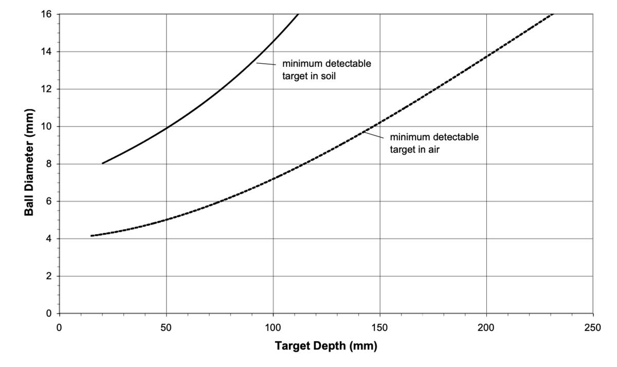
8.3 Detection capability for specific targets in soil
8.3.1 Principle
The objective of this test is to measure the maximum detection depth of any given target for the metal detector, sensitivity setting and the soil being used. This test is an in-soil analogy of 6.6. The maximum detection depth (plus sweep height) may be compared to the maximum detection height in air, in order to measure the effect of the soil on the detection capability for that target.
8.3.2 Equipment and test area
The requirements for the soil test area are defined in 8.1.2 above.
The detector shall be positioned and moved with a mechanical device or swept manually, as described in 8.1.3. The targets to be used for this test are:
-
the "ITOP" test targets [11] specified in B.2,
-
any other specific target of interest.
Any device enabling the depth of a target within the soil to be varied will displace some soil volume. If the amount of soil displaced is too large, the test ceases to be valid. It is therefore impractical to conduct this test for large targets, such as complete simulated mines. This test is more suited to small metal parts.
8.3.3 Procedure
Using the procedure as in 8.2.3 above, the depth of the target shall be varied until the maximum detection depth is determined.
8.3.4 Test results and reporting
The maximum detection depth for each target shall be recorded and compared to that obtained in-air for the same target using 6.6. An example test form is given in Annex D.5.
Record whether a manual or mechanized method was used to sweep the detector.
8.4 Fixed-depth detection test
8.4.1 Principle
The objective of this test is to determine the detection capability of the metal detector for buried test targets at fixed depths in a given soil. The detection capability is therefore expressed simply as target detected or not detected at the test depth. The test is an open test (not blind).
8.4.2 Equipment and test area
The requirements for the soil test area are defined in 8.1.2 above.
The detector shall be positioned and moved with a mechanical device or swept manually, as described in 8.1.3. The targets to be used for this test are:
c) the "ITOP" test targets [11] specified in B.2,
d) any other specific target of interest, including complete simulated mines or real disarmed mines.
8.4.3 Procedure
For fixed-depth detection tests on specific targets, the targets shall be placed at one or more of the standard depths of 0 mm (surface-flush), 50 mm, 100 mm, (130 mm – see B.5), 150 mm and 200 mm below the surface. If the detection performance of the metal detector under test is to be determined for large deep-buried metal targets such as anti-tank mines, the corresponding test targets shall also be buried at 300 mm below the surface. The positions of the targets shall be marked on the surface above the targets with non-metallic markers (e.g. plastic discs).
Adjacent targets shall be separated by a minimum of 0,5 m (see B.5). Targets shall be buried far enough from the edge of the test area to ensure that no interference is caused by the edge. A distance of 0,5 m should be sufficient.
If targets are used that are not rotationally symmetrical, the orientation of these targets when they are buried shall be recorded and reported. The depth of the targets is defined as the distance from the soil surface to the top of the targets when buried.
The locations, depths and orientations of the targets shall be measured whenever they are dug up for removal from the test area and the measured locations, depths and orientations shall recorded.
As well as the exact target locations, the extent of the detection halo (as specified in B.6) shall be indicated (e.g. with markers of another colour or with a disc-shaped marker under the actual target marker).
The detector shall be set up according to the general procedure (8.1.5 above). If applicable, the settings used shall be recorded.
The detector head shall be swept over the test area at a height of 30 mm.
The operator shall decide whether an alarm indication occurs when the detector head moves over a target (i.e. occurs above its detection halo).
The operator shall also report alarm indications not occurring above a target detection halo. Any such false indications shall be investigated. If found to be due to the soil (rather than an extraneous metal piece), the detector shall be re-adjusted where possible, to ensure that the soil being used does not trigger the alarm. The test shall then be restarted.
8.4.4 Test results and reporting
Record the actual target details and locations and for each target "detected" or "not detected" as appropriate. An example test form is given in Annex D.6.
If alarm indications occur that can not be related with one of the known targets, i.e. occur outside the detection halo of the targets, even after the readjustment procedure specified in 8.4.3 above, these indications shall be recorded with their location for further investigation.
Record whether a manual or mechanized method was used to sweep the detector.
8.5 Detection reliability tests
8.5.1 Principle
The objective of detection reliability tests is to evaluate the detection reliability of the metal detector when used by an operator who does not know the location of the targets. These tests are statistical performance tests in which the effect of environmental and human factors is added to the intrinsic capability measured by open tests such as 8.4 above.
Detection reliability tests are typically performed in or near to an area to be cleared of mines, in representative local soil and with targets representative of the local mine threat. Such tests may be part of either "consumer report" trials or "acceptance trials".
The possible output of a metal detector as used by an operator can be classified as follows:
-
true alarm indication (true positive) – a detector alarm from the presence of a metal object,
-
missed target (false negative) – no detector alarm in the presence of a metal object,
-
true negative – no detector alarm when no metal object is present,
-
false alarm indication (false positive) – a detector alarm when there is no metal object present.
For blind detection tests, numbers of realistic targets are buried in soil at specified depths and the reliability of detection is measured in terms of the true alarm indications, the missed targets and the false alarm indications recorded by the operator. A detector with high detection reliability is one that maximizes the number of true alarm indications and minimizes the number of false alarm indications.
This is a test of the detection reliability of metal detectors to detect metal in any amount. The detection of any metal object shall be regarded as a true indication of detection. It is therefore important that the test areas are free of metal objects other than the placed targets. Non-metallic objects present in the soil (such as magnetic pebbles) which may cause alarm indications on some detectors, shall not however be removed.
In order to obtain most value from the blind detection tests, the results of previous in-air (section 6) and in-soil (sections 8.3, 8.4) tests on the detector, giving maximum detection depth of targets, shall be borne in mind when designing the test.
8.5.2 Guidelines for test lane preparation
A site shall be chosen for the tests at which:
-
the native soil at the test site is representative of an area to be cleared of mines (the test site may be within that area), or
-
soil representative of the region requiring mine clearance has been placed in test lanes. Note that if soil is moved, the metal detector response will not necessarily be the same as it was prior to being disturbed.
The soil in which it is most difficult to detect mines (the most noisy) found in the mine-affected area should be used where possible. Either the test site should be set up in an area of that soil, or that soil should be all be transported and used in a test lane.
To determine the effect of the soil on a given detector, an in-soil sensitivity curve for the soil as specified in 8.2 shall be measured.
The vegetation over lanes shall be removed or cut short (so as not to impede sweeping at normal height – see B.5). Any metal objects on the soil surface shall be removed. Following this, using a metal detector, remove any buried metal objects. In some cases, during this clearing procedure, detection signals may come from the soil itself and be mistaken for metal. Therefore, some judgement will have to be exercised in determining how much effort is spent on metal object removal to minimize alarm indications from sources other than the placed targets. The goal is a test site free of metal objects other than the targets placed intentionally, so that detection of mines can be assessed.
If soil is brought in from another area for construction of the test site, the soil should be compacted so that it resembles as far as practicable the state found in an actual demining area – although this does not guarantee to give the same metal detector response.
The test areas used for blind detection tests shall comply with the requirements of 8.1.2 above as a minimum. However, in order to perform such testing effectively a large area is needed, which should be divided into well- defined test lanes. Corner locations of the test lanes can be marked with non-metallic corner posts or pegs. These stationary markers serve to define the test lane boundaries and are used as the reference points for measuring actual target locations and locations at which target detections are declared.
Lane width should be 1,5 to 2 m and depth at least 0,5 m. The width and depth of the lanes are so specified to ensure there is no effect from the indigenous soil of the test site (if different from the soil in the test lane) on the detector during the test. The area within the lane used for testing – i.e. where targets may be buried - should be a 1 m-wide strip, positioned in the centre of the lane. The length of the test lane will be determined by the number of test targets in each lane (by individual types and numbers for multiple encounters).
A training and calibration area should be established where detector operators can practise using the detectors assigned to them for the test. The area should include a metal-free area as specified in 8.1.2. In addition there should be a similar area containing targets as used in the test lanes. This area should be located away from the test lanes to minimize the possibility of operators picking up clues as to where mines are buried in the test lanes to be used for blind tests.
An accurate method is required to measure and record the placement of test targets and to record the location of detections declared during the field trials. A laser-based total station survey system is ideal for this purpose. Three or four reference benchmarks outside the lanes should be measured immediately before and after each set of lane- corner, target, or detection-marker measurements to confirm data integrity and provide some chance of data recovery due to operator error. If such a survey system is not available, 100 m, non-stretch tape measures should be provided to measure these positions relative to the reference point. These tape measures are also required to facilitate the laying out of the test site
8.5.3 Target types
The following types of targets shall be used:
- Standard test target(s) simulating metal mine components as specified in B.2. The target or targets with the closest response to the local threat mines, as determined in in-air tests.
- Specific mine test targets (B.3), whether simulated mines or disarmed mines. Disarmed mines representative of the local threat.
8.5.4 Depth, orientation, and separation of targets
This section specifies blind tests for target detection reliability. A prior open test may be required however, to determine whether detection of a given target is possible at all at a given depth in the local soil. Any such test shall be performed according to 8.4 above. Testing with targets at depths of 50 and 100 mm more than those derived from the in-air maximum detection height should ensure that the depth range used spans the maximum detection depth.
Orientation of buried mine targets shall be as normally laid – horizontal with activation device uppermost.
Separation of targets in the test lane shall be large enough to ensure that the detector under test cannot give an alarm indication due to the response from two targets at the same time. The separation shall be at least 0,5 m.
Targets shall be buried at one or more of the depths specified in B.5, depending on local clearance depth requirements, the mine types of interest and the results of in-soil maximum detection depth measurements as specified in 8.3.
For each target type buried, at least seven (7) identical targets shall be buried at the same depth. At least 28 targets shall be used in each test soil. This minimum number could be composed of four target types, each with seven identical specimens, all at the same depth. Alternatively this number could be made up of identical targets, with seven at each of four burial depths.
As mines are buried, their location shall be accurately noted. The location shall be expressed as down-lane and cross-lane measurements from the end and sides of the test lane (using the corner posts or pegs as datum points). The mine types and depths shall be intermixed randomly down the length of the lane. The measurement of each mine’s actual location, its type, and its depth, shall be recorded for each test lane. Access to this information shall be restricted to personnel managing the test and shall not be disclosed to any of the detector operators participating in the test.
Once the test targets are laid in the test lanes, all visual clues that might indicate a mine’s presence shall be removed. Sweeping, or lightly raking the test lane surface can remove such clues. If tests extend over a period of days, lanes shall be inspected daily to remove clues that may result from settling, rain, and other causes. Even with these safeguards, telltale clues can still occur. Therefore, detector operators shall be told that the test is to measure detection reliability of the detector (and is not a test of individual operator performance) and therefore to ignore any visual evidence of target location.
8.5.5 Operators
The operators of the metal detectors shall be capable of using the detector as intended by the manufacturer but should be representative of the operators that would use the detector in the field. The goal of this CWA is to provide an objective evaluation of the capabilities of the detector. However, since an essential part of the detector operation is interpretation of alarm indications by the operator, variable human factors are introduced. In order to minimize the effect of a single operator on the results, at least three (3) operators shall use each detector type. The recommended number of operators is six (6). If possible, all of the operators should operate each detector in each test lane.
Operators should be trained on the proper use of each detector that they will operate during the blind detection test. They should have adequate time to become familiar with the detector operation, assure themselves that each detector is able to detect mines in a calibration area and to attune their ears to the sounds of the detectors. Record the name of the operators for each detector and the test lane number.
NOTE Deminers in any given demining operation are frequently familiar with specific detectors. This familiarity could affect the results of a test. Therefore, the make and model of the detector they have been using shall be noted.
8.5.6 Test procedure
At the start of each test, the detector shall be set up according to the manufacturers instructions as given in the operation manual. The detector shall be adjusted for the maximum sensitivity attainable on the soil of the test lane by performing the procedure given in section 8.1.5. After the detector is adjusted to the soil conditions, the in-air sensitivity shall be measured according to 6.3.3 and 6.4.
The test shall be performed by an operator using the detector manually.
The detection tests shall be blind; that is to say the operator shall not know the location of targets laid in the lane prior to searching for them with the detector. The operator shall be supervised at all times by personnel managing the testing.
Each detector shall be used in its normal operating mode, sweeping manually in a transverse direction at a speed that ensures optimum detection capability (see Sections 6.4.2 and 6.4.3) at standard sweep height (B.5). The operator shall move the detector forward along the test lane between sweeps. The distance in the forward direction between successive sweeps shall be small enough to ensure that the high-sensitivity region of the sensor head covers all of the ground. The appropriate sweep overlap may be determined by measuring the sensitivity profile according to 6.7.
The operator shall attempt to detect all of the targets in the test lane. When a operator makes a detection he/she shall try, to the best of their ability and the capability of the detector, to determine the location of the centre of the target detected. A non-metallic marker shall be placed on the ground to mark the detection location.
The direction in which any single operator moves down a lane shall be alternated (bottom to top, top to bottom) with each pass. This will make it harder for the operator to memorize locations where he/she has previously detected a target. Blind tests shall not be observed by other operators for the same reason. The only observers shall be test personnel.
After each traverse of the blind test lanes, test personnel shall measure the location of each marked detection, record the measurements, and retrieve the markers. After each test, the recorded test detections and their locations shall be compared to the actual locations of the targets laid, to determine the test results. This process shall be repeated for each detector in each soil type. If possible, the test shall be performed with at least two (2) examples of the same detector model. The test shall be performed at least twice for each individual detector with each operator. If more than one sensitivity setting of an individual detector is used during the tests, the test at each setting shall be repeated twice for each operator.
When the test is over and as the targets are removed, the identity and position of the removed targets shall be verified and compared to the original location measurements. Should there be any discrepancy, the test results shall be corrected as appropriate.
To account for uncertainty in locating the origin of signals from the targets, use shall be made of an detection halo measured from the centre of each target. The radius of the detection halo shall be as specified in B.6. Any mark placed within the halo for a given target shall be declared a true indication (i.e. a successful detection) for that target. Any mark outside the halo shall be declared a false indication. All true indications and false indications shall be recorded and tallied as shall the cases of missed targets.
If locations in the test lane give persistent false indications, such locations shall be investigated to ensure that there is no metallic object that has been inadvertently left there. If such an object is found, all reported indications of prior tests that correspond to this object (within detection halo) shall be omitted from analysis of the results.
8.5.7 Test results, reporting and evaluation
For each detector tested and each target/depth/soil combination, the following shall be reported;
-
the number and locations of true indications (for all operators),
-
the number and locations of missed targets (for all operators),
-
the number and locations of false indications (for all operators).
8.6 Additional detection reliability testing
The basic level of testing described above provides a common base of detection reliability test that will enable comparison of test results of detectors to be made between different trials and locations (suitable for "consumer report" trial).
To satisfy the local deminers’ needs to know the capability of the detector being tested as applied specifically to their local conditions, the basic testing may be augmented with more operationally-oriented field testing that has been tailored by the local MACs and NGOs with input from local deminers i.e. for an "acceptance trial" for local requirements.
The main categories in which these additional tests may be carried out include:
-
increasing levels of vegetation (if any mine clearance operation with metal detection is carried out with significant vegetation levels still present),
-
increasing roughness of terrain,
-
multiple emplacements of mines with minimal separation
-
various orientations of mines, other than simply horizontal
-
metal clutter rejection test (requires definition of a clutter threshold in terms of standard targets)
In all cases, open testing shall be performed prior to blind reliability tests.
9. Operational performance characteristics
9.1 General
9.1.1 Principles
There are several types of test that may be performed in an operational or "in-field" environment. It may be necessary to make tests of the ability of a metal detector to detect targets under certain conditions, either in-air or in-soil. Such tests are described in sections 6 and 8, with guidance for how to do the tests manually in field conditions.
Other simple tests may also be performed to measure detector performance with specific local conditions and targets. These tests are specified in this section.
The area shall be as free as possible from any electromagnetic interference and the risk shall be minimized by turning off unnecessary equipment and locating the test as far as possible from operating equipment, except where the effects of such interference are being tested.
For each test, measure maximum detection height in air at the sensitivity used for the test, using the target specified in 6.4 and according to 6.3.3.
9.1.2 General reporting requirements
Although the tests in this section tend to be performed in conditions that are less controlled than the "laboratory" tests specified in Section 6 for example, all conditions shall be recorded accurately. The following measurements (in ISO metric units) and other information shall be recorded before and during the tests.
-
The test site location (for example, latitude and longitude).
-
Meteorological conditions; temperature soil/air, barometric pressure, wind speed and direction during tests.
-
Description of any unplanned events (equipment breakdowns etc.) occurring during the tests
-
Safety and human health precautions taken.
-
Incidental observations on climatic suitability, ease of transportation & handling and ease of maintenance in accordance with Section 10.
The data collected shall be presented where necessary for each test procedure using text commentary, tables, photographs, video, charts, and graphs as appropriate. The collected data shall be summarized for each individual test. Models and other statistical techniques shall be described in a sufficient detail to enable the reader to understand the basis for the analysis.
9.2 Target location accuracy
9.2.1 Test principle
The objective of this test is to measure the accuracy to which the detector can locate the position of an obscured target. The test gives a measure of the inherent location accuracy of the detector using a point-like target. The results can be used for comparison of detectors, but do not indicate the accuracy that will always be achieved in locating other, extended targets in actual demining operations.
The method used to perform these tasks shall be as described in the detector manual for locating the metal object causing an alarm indication (often known as "pinpointing").
The accuracy with which these tasks can be performed will depend upon the experience and skill of the operator. As for the detection reliability tests described in Section 8.5 above, the operator skill will influence the test results, so this effect should be mitigated by the use of several operators (at least three (3)).
9.2.2 Test procedure
The target shall be a point-like metal object, in that its dimensions shall be very small compared to the dimensions of the metal detector sensor head. The target shall however give a big enough response to be clearly detected at the sensor heights above target used. An examples of such a target is the steel pin from the ITOP O0 insert as specified in B.2 (0,2g, 14mm length x 1,6mm Ø).
One test shall be performed with the target immediately below the sensor head (<10 mm) and another at a 50 mm sensor height above target. As the test is blind, the target area must be covered, or some other means employed to prevent the operator seeing evidence of the target.
The test shall be performed either in-air (at least 0,3 m above the floor or ground), or in-soil.
The target shall be randomly placed in a frame or jig and obscured by a cover over which the detector sensor head can be swept. The detector shall be swept over the test frame in two perpendicular directions and the target located according to the recommended practice for that detector as specified in the manual. The distance from the measured target location to the actual target location shall be subsequently measured and the test repeated with new target co-ordinates.
A suggested way of performing this test is to construct a wood or plastic frame within which the target may be placed randomly on a grid on a sheet of ISO A5 format paper. For tests in soil, the frame is placed on the soil over the marked target position. The target is placed in one of the grid squares according to randomly generated co- ordinates.
The target is covered with a transparent acrylic sheet to give the appropriate sensor height above target. A sheet of tracing paper is fixed over the cover. The target is obscured with a sheet of paper between it and the cover. The target is located using the metal detector and the position marked on the tracing paper. The target is the uncovered so that the distance between the marked point and the actual position of the centre of the target can be measured.
If the test is performed on and in soil, the marking of the position of the target is likely to be less accurate and this will be reflected in the results.
The test shall be repeated five (5) times for each operator, with the target location changed each time. The mean distance from the actual location shall be recorded for each operator.
9.2.3 Test results and reporting
The distance between the actual and measured locations shall be recorded for each attempt. The mean location error and scatter shall be recorded. If the test is performed in soil, the characteristics of the soil shall be recorded as specified in 8.1.4. An example test form is given in Annex D.7.
9.3 Shape determination of targets
9.3.1 Test principle
The objective of this test is to determine the capability of the detector to discriminate between obscured point-like, linear and two-dimensional (disc) targets.
The method used to perform these tasks shall be as described in the detector manual.
The accuracy with which these tasks can be performed will depend upon the experience and skill of the operator. As for the detection reliability tests described in Section 8.5 above, the operator skill will the influence the test results, so this effect should be mitigated by the use of several operators (at least three (3) recommended).
9.3.2 Test procedure
Three targets shall be used for the shape determination test as specified in B.4; a steel ball, a rod and a disc. The targets shall be placed at two depths in the soil for the performance of this test; at the surface and at 50 mm. The rod and disc targets shall be placed horizontally. This test may also be performed in air.
Targets shall be placed randomly on a plot of metal-free soil at locations not revealed to the operator. The placement of targets and the sequence of testing shall be made so that it is not possible to guess the type of the target by a process of elimination, based upon the results for targets of which he has already determined the shape.
The detector shall be used as in minefield searching and swept across the lane. When the target is detected, the operator shall use the manufacturer-recommended procedure to locate the target extent and to determine therefore whether the target is point-like, linear, or planar.
Each target type shall be identified at least three (3) times, either by repeating the test with the same targets at different locations, or by using many targets.
9.3.3 Test results and reporting
The capability for characterization of targets into point, linear and planar shall be recorded as a percentage of correct classification for each shape. The medium in which the tests is performed (air or soil type) shall be recorded. An example test form is given in Annex D.8.
9.4 Resolution of adjacent targets
9.4.1 Test principle
The objective of this test is to determine the capability of the metal detector to discriminate between targets that are buried close to each other. Both targets of similar size and targets of different size are considered. The minimum target separation distance at which the targets can be resolved is measured.
9.4.2 Test procedure
The test is performed blind - the target separation shall not be revealed to the operator.
The "small" target shall be a 5 to 10 mm diameter chrome steel ball as specified in B.1.
The "large" target shall be a steel disc as specified in B.4, or a target representative of a high-metal local threat.
The targets shall be placed a) on the surface, b) at a depth of 50 mm. The discs shall be buried horizontally.
The resolution for two configurations shall be measured; between two small targets and between a large target and a small target.
The two targets shall be placed on the surface or buried as applicable and the detector shall be swept over the pair of targets in all directions to try to resolve them. For the surface-placed targets, the targets shall be moved until the minimum separation is achieved, at which two resolvable alarm indications from the targets are still produced. For the buried targets, either one target has to be unearthed and re-buried each time to change the separation, or the test can be made using several pairs of targets at different separations.
The alarm signals from the two targets shall be clearly resolvable at the minimum separation. To be resolvable, there shall be either no alarm indication at all between two test targets, or a clear "minimum" in the tone and/or amplitude of the alarm, according to the detector design
9.4.3 Test results and reporting
The minimum resolvable separations (the distance between the target centres and also between edges for the targets used) for all four combinations of target pairs and depth shall be recorded;
-
two small targets at the surface,
-
small target and large target at the surface,
-
two small targets at 50 mm depth,
-
small target and large target at 50 mm depth. An example test form is given in Annex D.9.
9.5 The influence of specific media on detection
9.5.1 Test principle
Tests to determine the effect of soil on the detection performance of metal detectors are specified in Section 8 above. In a field situation it may be necessary to know the effect of a particular local ground condition on the sensitivity of a detector. For example the effects of magnetic soil, bricks and other masonry, fired pottery, isolated magnetic stones/rocks etc. on the capability for detecting targets beneath these materials may need to be known
The following tests will give a description of approaches for testing detectors under such specific conditions.
The objective of these tests is to define the influence of soil or other medium on the detector performance and the ability of the detector to adjust to these conditions. The first test is a repeat of the in-soil tests in the specific medium encountered. The second test is specifically to determine the effect of a heterogeneous medium (isolated magnetic stones etc.) on the detector.
9.5.2 Procedure – test 1
The tests shall be carried out in areas where the conditions are known made as and close as possible to the real minefield environment. The electromagnetic soil properties shall be measured and recorded where possible according to Section 8.1.4. The test area is to be checked and prepared as given in the general test conditions in 8.1.2.
The test area preparation shall mimic the structure of the demining scenario of interest. For example if the detection capability through a layer of bricks needs to be tested, then targets shall be placed beneath such a layer of bricks.
In-soil tests of the types specified in 8.2 (sensitivity curves) and 8.3 (detection of specific targets at fixed depths) shall be performed as required. In particular, the use of targets simulating the response from mines/UXO that form the local threat.
9.5.3 Procedure – test 2
A particular situation against which to test performance, is the presence of isolated stones in the soil that have a strong influence on detectors. A medium with such heterogeneous electromagnetic properties, for example with highly-magnetic stones in a relatively weakly-magnetic soil places a greater demand on the soil-rejection capability of the detector than does a homogeneous medium.
A test lane shall be prepared, containing the magnetic stones or other discontinuities for which the test is to be performed. The sizes of the stones used shall be representative of the situation in an area to be cleared of mines. The stones shall be buried flush with the soil surface.
The metal detector shall be set up as normal (8.1.5). The detector shall then be swept over the stones and, if necessary, the detector shall be adjusted until the stones do not give an alarm indication, according to the specific soil-rejection method used for that detector. If it is not possible to eliminate the signal from the stone in this way, this shall be noted and the test discontinued.
With the settings unchanged, detection tests shall then be performed as in 8.3 on the targets of interest. These tests shall however include; tests on targets in areas of soil free from stones (more than 0,3 m between target and stone), tests on targets beneath (or next to) stones and tests on stones alone to verify the rejection of their signals.
9.5.4 Test results and reporting
The result assessment for test 1 shall be as for the in-soil tests, the sensitivity curves and/or the detected/not detected results for targets at fixed depths.
For test 2 for the detection of target(s) when the detector is set up to reject the signal from an isolated magnetic stone (or similar), the results for detection of targets away from and next to stones shall be recorded.
9.6 Detection near large linear metal objects
9.6.1 Test principle
The capability of the detector to perform in the vicinity of large linear metal objects may be required in urban areas. Such situations include pipelines, railway tracks, power pylons, pipes, conduit, reinforced concrete etc. This test aims to determine the extent to which a detector can work under these conditions without losing sensitivity. The possible working proximity will depend on the amount of metal in the targets. Targets should therefore be selected in accordance with the main threat in the area.
Many metal detectors employ designs of coils that make them comparatively insensitive to metal objects with an equivalent influence on both parts of the coil design. Other detectors use high-pass filtering or auto-zero techniques to remove signals that vary little with time. Detectors with such designs can in principle be used close to (and swept parallel to) large linear metal objects and still detect smaller targets. The objective of this test is to determine the effectiveness of such designs as well as more conventional metal detectors.
The test may be used to measure this capability for a particular target of interest (a local threat). The test may also be used as a general test of the capability of detectors to detect targets in this scenario.
This test measures the critical distance at which the detector can just discriminate between the signal from the linear object and the signal from the test target.
9.6.2 Test procedure
Where possible the test target shall be selected to have equivalent response to the mine threat expected in the area. Other targets simulating mines may also be used.
If the test is to be used as a general test for detection capability (not for a specific target), then a chrome steel ball as specified in B.1, with diameter 10 mm shall be used as the target.
A steel bar with minimum length 2 m and arbitrary cross sectional shape, but with cross sectional area 10 mm (min) × 10 mm (min) shall be used to represent a large linear metal object.
The targets shall be buried a) flush with the surface and b) at 50 mm depth. The bar shall be positioned on the soil surface, with the target closest to the middle of the bar (at least 0,5 m from either end). Initially the bar shall be kept far from the target position (>0,5m).
This is a blind test, the operator is told that the target is in the test area, but the exact location of the target is not revealed. The detector shall be swept in the normal operational sweep direction, parallel to the bar, over the test area. An alarm indication from the target shall be obtained and the operator shall locate the target as in 9.2.
The linear target shall then be moved progressively closer to the target and the sweep repeated until the point where the bar is causing an alarm indication. The bar shall be moved to obtain the closest distance at which an indication is produced from the target but not the bar.
9.6.3 Test results and reporting
The minimum horizontal perpendicular distance from the bar to the true target location shall be recorded, at which
an alarm indication from the target but not the bar is obtained. An example test form is given in Annex D.10.
If the target position is not located initially within 50 mm, then any minimum target-to-bar distance subsequently measured that is less than this shall be rejected as being unreliable.
9.7 Effect of specific electromagnetic interference sources
9.7.1 Test principle
Radio communication is necessary and is used in every demining operation. Radios of various types are used on- site for maintaining communication between the sites and the operating base. It is possible that these sources of radio-frequency fields may interfere with the detector, causing alarm indications or other effects.
Power lines and other power-supply equipment (transformers, switch-gear etc) are possible sources of electromagnetic interference for metal detectors.
NOTE The interference from power supply equipment may be dependent on the current load at which they are operating. Unless the load is known at the time of the test, the test is poorly-controlled.
The objective of this test is to determine the minimum distance from any such specific source of interference at which the detector can be used.
9.7.2 Test procedure
The detector shall be set up in accordance with the user manual and adjusted to the local soil as in 8.1.5. The in-air sensitivity shall be measured according to 6.4.
If the potential interference source is a radio, it shall be switched on and used as normal.
If the detector is being tested for interference from a suspended power line, the lowest point of the line shall be used as a reference point
The source shall be approached by the operator sweeping the detector as normal. When interference from the source is produced, the detector shall be moved away again until it stops.
If the source is a power line, the operator shall move towards the power line, in a direction perpendicular to the line.
9.7.3 Test results and reporting
The detector sensitivity for the test, as measured by maximum detection height in 6.4.1 shall be recorded. If interference is caused by the potential source, this fact shall be recorded. The minimum distance at which the detector is free of interference from the source shall be recorded.
The operating state of the potential interference source shall be recorded where available – e.g. radio type, power settings and frequency used; current load in power lines.
9.8 Mutual interference between detectors
9.8.1 Test principle
In normal operation, deminers working with their detectors are kept far apart.
If an accident occurs, however, it may be necessary to approach an injured deminer across ground that is not cleared using a detector to ensure this approach is safe. If the injured deminer's detector is still switched on, there is therefore the possibility that the two detectors get close together during this recovery procedure.
The objective of this test is to establish the closest working distance of one detector to another working detector. Some pairs of detectors may affect each other less than others, so the best suited (least-affected) detector may be selected and prepared in case it is needed for such recovery operations.
9.8.2 Test procedure
The test requires a stationary detector and a moving detector. The test determines the effect of the stationary detector on the moving detector.
The stationary detector shall be set up to the highest in-air sensitivity possible without the alarm being triggered. The detector shall be laid on the ground or kept off the ground to prevent alarms from the soil, with the coil axis of the search head directed in the approach direction of the moving detector.
The moving detector shall be set up to maximum in-air sensitivity possible without the alarm being triggered, at a position remote from the stationary detector (a distance of at least 15m).
The search head of the moving detector shall be directed towards the stationary detector and moved closer. With the first audible signal of interference the operator shall stop moving and determine the minimum distance between the detectors at which no interference is heard. This distance shall be recorded. This test shall be repeated five (5) times.
This test should be repeated for different combinations of detector types.
9.8.3 Test results and reporting
The mean minimum distance shall be recorded at which the moving detector does not experience interference from the stationary detector. It may be found that for each detector type used as the stationary detector, there is another detector type that can approach closest without interference. This result shall be recorded. This information would be valuable for safe completion of the recovery procedure described in 9.8.1 above.
10. Evaluation of ergonomic and operational aspects
10.1 Robustness testing
The objective of testing for robustness is to determine whether a metal detector is sufficiently robust for the rough treatment it will experience in operational use and being transported in the field. Testing shall not be only functional testing, but measurement of detection capability shall also be made to determine whether the test has degraded the detector performance.
Evaluation of the results is straightforward. For any detector to cease to operate or to lose detection capability is undesirable. Any visible damage shall also be noted. Comment also on potential weak points in construction and reparability of the detector.
10.1.1 Shock and bump tests
The objective of the shock test is to determine in a controlled test whether the detector can withstand a mechanical shock without degradation in performance. The objective of the bump test is to determine in a controlled test whether the detector can withstand repeated bumping, such as that likely to be encountered when the detector is transported loose in a wheeled vehicle, without degradation in performance.
If such testing is required, existing standards specify methods for performing these tests. The following tests are given as guidance, consistent with the specifications for hand-held metal detectors in [9]:
-
Test the detector in accordance with the requirements of IEC 68-2-27:1987, using the half-sine pulse shape with a nominal peak acceleration of 300 m/s2 and a nominal pulse duration of 6 ms.
-
Test the detector in accordance with the requirements of IEC 68-2-29:1987, using 100 bumps, each with a nominal peak acceleration of 400 m/s2 and a nominal pulse duration of 6 ms.
The detection capability shall be measured and recorded before and after shock and bump tests according to Section 6.4 to determine whether there is any change.
10.1.2 Drop tests
Where the facilities are not available for the full testing of detectors according to the above specifications, the following simpler, but less-controlled tests shall be performed. The objective of these tests is to determine whether the dropping the detector causes any damage or degrades the performance
-
The detector shall be packed in its transport case and held 1,8 m above the ground. It shall then be dropped onto hard ground (metalled road or hard-packed earth and/or stones). The drop shall be repeated five (5) times with the case in different orientations. The case and detector shall be inspected for any visible signs of damage and any such damage recorded.
-
The detector shall be held horizontally 1,2 m above the ground. It shall then be dropped onto hard ground (metalled road or hard-packed earth and/or stones). The drop shall be repeated five (5) times with the detector always held horizontal but in different orientations, so that different parts of the detector hit the ground. The detector shall be inspected for any visible signs of damage and any such damage recorded.
The detection capability shall be measured and recorded before and after drop tests according to Section 6.4 to determine whether there is any change.
10.2 Guidelines for evaluating ergonomic and operational aspects
Testing performed in order to evaluate ergonomic and operational aspects of the metal detector shall proceed as follows:
-
Determine whether it is a simple-to-operate and compact device.
-
Is the detector a single unit, or does it have a separate unit to be attached to a belt, for example? Evaluation: some operators prefer a single unit, others prefer to have a separate belt pack to reduce the weight in the hands.
-
Is the detector easy to operate in standing, kneeling and prone positions? Record the time taken to change between the detector configurations for the different operating positions.
-
Measure the operating mass of the detector (kg).
-
Determine the balance point of the detector when operating and measure the moment(s) (in Nm) at the detector handle(s). Evaluation: a detector balanced at the handle is less tiring to use than one for which there is a significant moment at the handle when the detector is being used.
-
Measure the moment of inertia (in kg.m2) of the detector about its axis of rotation while sweeping in the different use positions. For example when standing, the axis of rotation is usually at the elbow or shoulder of the operator. Evaluation: even if balanced, a detector with a high moment of inertia (high mass at distance far from the axis of rotation) is tiring to sweep, because a large torque (moment) needs to be applied to decelerate and accelerate the detector at the end of each transverse sweep.
-
Determine whether the detector can be operated easily and comfortably by operators having a range of stature (consider likely stature of users) and by left-handed operators.
-
Consider whether an operator with a low level of literacy and/or technical education would be able to use the metal detector easily.
-
If it has an audio detection-alarm, whether the sound level is adjustable to zero. Evaluation: if the sound level is adjustable to zero, this may be done unintentionally during operation and is therefore potentially dangerous.
-
What level of hearing is required to operate the detector correctly. Evaluation: a better detector is one that can be used even by someone with less than normal hearing.
-
Determine whether there is a warning alarm or automatic switch-off for low battery condition. Evaluation: is it possible for the operator to use the detector in low battery condition?
-
Determine whether there are any error-mode indications.
-
Determine whether there is an indicator for proper functioning of the detector (e.g. a confidence tone). Evaluation: a confidence tone of some sort is preferred. If the detector makes no sound or other indication while operating, it is not clear to the operator that it is working.
-
Record the type of batteries that can be used. Evaluation: it is difficult to get good-quality alkaline batteries in many remote locations. Can the detector operate also on rechargeable or carbon-zinc batteries – even if this means shorter operating time?
-
Determine whether the detector has an adjustable shaft and protected cables. Evaluation: an adjustable shaft is necessary for use in different operating positions. Cables that can snag on obstructions or on part of the detector during assembly/disassembly get damaged are a disadvantage.
10.3 Interchangeability of parts
The objective of this test is to determine whether nominally-equivalent parts of a detector are physically, electrically and functionally interchangeable. This is an important aspect when trying to service detectors in field conditions, where spare parts may be difficult to obtain, so parts are "cannibalized" from other detectors. The simplest example of this is using a sensor head with a different electronic control box from the one it was delivered with.
To test the effect of the exchange of any one part in the detector with another of the same part number, the detector shall first be set up to maximum in-air sensitivity according to the operation manual. The detection sensitivity shall be measured according to 6.4.
The detector shall then be switched off and the part in question shall be replaced with the other part bearing the same part number.
If it is not physically possible to replace the part, this fact shall be recorded.
On replacing the part the detector shall be re-assembled, switched on and set up to maximum in-air sensitivity as before. The sensitivity shall be re-measured and recorded. Any change shall be noted.
The expected result is that any part with the same part number should be physically interchangeable. Due to the tolerance on the manufacture of some (particularly electronic) components, it may be necessary to trim the circuitry after component replacement to obtain optimum performance. In this case direct replacement without the facility to optimize may result in poorer performance.
Annex A: Test soils
A.1 General
The methods for measuring the effects of soils specify tests that quantify the detection performance of a detector in combination with a particular soil. In order to make comparisons between detectors; tests of those detectors need to be performed on the same soil or on plots of soil with the same electromagnetic properties.
The soil in test areas shall be flat with height variation being less than 20 mm in any 0,3 m horizontal length. The soil in the test areas shall be homogenous except where testing of controlled heterogeneity is performed.
NOTE Tests on homogenous soils alone can produce misleading results of metal detector performance.
A.2 Soil types
Testing of metal detectors may be performed on any soil considered to represent a general or specific type of soil present in a mined area.
The type of soil shall be recorded (sand, silt, clay, loam, peat, bauxite, laterite) as shall its moisture content at the time of the test.
Artificial soils made from mixtures of non-magnetic soils, sand, clay or other media with magnetic minerals such as magnetite may be used to give soil media of controlled magnetic properties. The medium produced may not be very representative of any real soils however. In particular, it is difficult to reproduce the complex magnetic susceptibility (see A.3 below). This is an on-going research topic.
The electrical conductivity in S/m and the magnetic susceptibility of the soil (see A.3 below) in dimensionless SI units shall be measured before and after the tests. Instruments used to measure these properties shall be calibrated traceably to National Standards and used according to their operating manual.
Given the difficulties in measuring the soil properties that most affect metal detectors (see A.3 below), the assessment of soil type using a metal detector is often valuable. The detector used must be a one that does not have a ground compensation function (or has it turned off). The influence of the soil can be quantified by measuring the minimum height above the soil to which the detector needs to be raised to stop any alarm indications (Method used in [7]). This measurement is dependent on the detector used and the detector settings, so it does not give standard measurements of soil response that can be used as reference. However, this method can be used to classify soils locally.
A.3 Magnetic susceptibility of soils
Measurements of the magnetic susceptibility of soil are difficult to reproduce, as the measurement is not always independent of the measurement technique. This is usually because the volume of soil interrogated by the instrument may be heterogeneous. The measured susceptibility can vary with location and according to the measurement used.
In addition, measured susceptibility is frequency dependent. It is, in fact, the frequency-dependent (complex), behaviour of soil susceptibility that is important in some types of metal detector. A medium with a frequency- independent (real) susceptibility would not produce a response on this type of detector. Ideally therefore, the complex susceptibility (real and imaginary parts of the susceptibility) over the frequency range used by metal detectors should be measured. Unfortunately at the time of writing, no commercial instruments are known that can do so. Some instruments are available that will measure samples at two frequencies so that the "frequency dependent susceptibility" can be assessed in terms of a % change measured between the two frequencies.
Notwithstanding these difficulties, it is possible to classify soils roughly into ranges of magnetic susceptibility as measured by commercial soil-susceptibility meters and expressed as a single number. The susceptibility as measured in this way can only give a rough guide of the relative effect that the soil will have on a metal detector. It can happen that soil A gives a lower susceptibility meter reading than soil B, but soil A has a greater effect on a metal detector.
The coil dimensions of the susceptibility meter should be similar to those of the metal detector sensor head, so that the volume of soil interrogated is similar. The susceptibility classification is given below.
| Classification | Magnetic susceptibility (SI units) |
|---|---|
| Neutral | 0 to 50 10-5 |
| Moderate | 50 to 500 10-5 |
| Severe | 500 to 2000 10-5 |
| Very severe | Above 2000 10-5 |
The mass susceptibility is (volume) susceptibility divided by the density of the sample. This property is, in principle, independent of the degree of compaction of the soil. When laboratory measurements of soil samples are made, it is the mass susceptibility measurement that is most useful, since a loosely-packed sample will give a lower volume susceptibility than a compacted sample with the same composition.
For field measurements, it is the actual volume susceptibility in the state of soil compaction found that is of interest, since it governs how the soil affects a metal detector.
Annex B: Test targets
B.1 Parametric test targets
To measure the detection capability of a metal detector as it varies with target-to-detector height requires a set of simple geometric targets (see 5.6) of different size. This makes it possible to plot the maximum detection height against target size. The targets used shall be spherical metal balls. The acceptable tolerance on the steel ball sphericity shall be ±0,1mm.
Balls with diameters in the range 3 mm to 30 mm shall be used.
Balls of the following materials shall be used to evaluate the relative sensitivity of a detector to different metals:
-
High carbon, low alloy steel, also known as chrome steel (designations; UNS G52986, AISI 52100, UNI 100 Cr 6, DIN 1.3505) shall be used for the basic detection capability curve. Balls of this material are easily available all around the world and so it is straightforward to measure detection curves in field conditions. This is a ferromagnetic steel. Tests have shown [13] that balls of different ferromagnetic steels give practically indistinguishable sensitivity curves, so the curves are not sensitive to small variations in material properties. Many mine parts are made from ferromagnetic steel (e.g. striker pins).
-
Austenitic stainless steel (designations; UNS S31600, AISI 316). This metal has a low electrical conductivity and is essentially non-magnetic (effective magnetic permeability is approximately 1). Small parts of such metals are often difficult to detect.
-
Aluminium. Many mine parts, such as detonator tubes are made from aluminium. This metal is therefore important to be able to detect.
Additional materials of interest may be added for purposes of comparison. For example, lead and copper are found in some landmines. In every case the material specification shall be recorded.
B.2 Standard targets that simulate metal components of mines ("ITOPs")
Test targets shall be used that have the metal content typical of a class of mine. Such targets shall be selected from the set of test targets listed below. These targets are known as the "ITOP inserts" since they were conceived for an International Test Operations Procedure project as the metal content of larger simulant mines. The targets are defined in [11]. The targets are metal parts set in silicone within a plastic cylinder. The metal parts sit on the base of the cylinder. The cylinders were designed to be inserted into the bottom of a simulant mine and are marked with an engraved lid, which is therefore on the underside of the cylinder in normal use. When these ITOP inserts are used therefore, the engraved lid shall always be on the underside and the sensor height above the target and the target depth shall be measured to the top of the cylinder in this orientation (See Figure 11).
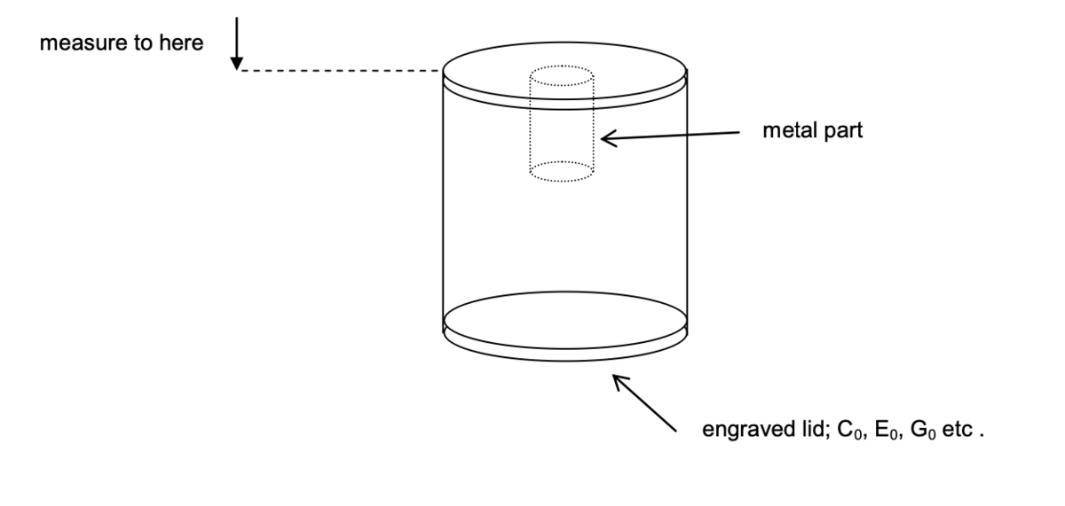
| ITOP Insert | Level of detectability | Metal Content |
|---|---|---|
| C0 | very difficult | carbon steel ball; diameter 3,2 mm |
| E0 | very difficult | vertical carbon steel pin; length 7 mm, diameter 1,6 mm |
| G0 | hard to detect | vertical copper tube; length 12,7 mm, outer diameter 3,2 mm, wall thickness 0,4 mm |
| I0 | hard to detect | vertical aluminium tube; length 12,7 mm, outer diameter 4,8 mm, wall thickness 0,38 mm |
| K0 | moderately difficult | Two (2) parts:
|
| M0 | moderately difficult | vertical aluminium tube; length 38 mm, outer diameter 6,35 mm, wall thickness 0,38 mm |
| O0 | easiest to detect | Four (4) parts:
|
B.3 Specific mine test targets
The response of metal detectors to specific mines that are a threat in a particular area often needs to be measured. In addition, the response to particular mines that are difficult to detect is of interest. In such cases the response of a detector to an actual mine that has been made safe is often measured. There are difficulties with this approach. It may be difficult or impossible to make the mine safe enough (to be transported freely, for example), while preserving the metallic components in the position they would be in the armed state. A target designed to have the same metallic content, in configuration and properties of the components, may therefore be used instead.
If the test target is, or is intended to simulate a specific type of mine, the location, orientation and electromagnetic properties of the metallic components within it shall accurately represent those of the metallic components within that specific mine in its normal armed state.
The ability of any given detector to detect real mines of a particular type may vary, since the metals used in the mine may not always be the same. In addition, corrosion of metal parts in mines that have been in the ground for several years will also make them harder to detect. The use of test targets to predict the ability of a detector to detect a real mine must always take this into account. For example, if a steel component in a mine is known to rust badly when left in the ground for several years, the signal from this component is likely to reduce. Modifying or even removing the component from a surrogate target to give the worst-case situation can simulate the response to the mine with a corroded component.
When a test target represents the metal component(s) from a particular type of mine, the metal piece(s) shall be mounted in an insulating holder or other means to reproduce the correct location and orientation of the component(s) from the top of the mine when in its normal armed state. The equivalent location of the top of the mine shall be clearly marked on any such holder or mount. The target-to-detector distance for detection shall then be measured to the marked “top of mine” point.
It is the metal content that is the most important aspect of targets for testing metal detectors. However, in some noisy soils with some detectors, the volume of soil displaced by the mine may have an effect on the detector response. Therefore a target intended to replicate the response of an actual mine shall also have a similar overall shape and volume.
If the test target is a generic simulation of a class or size of mine, the overall volume shall be typical of such mines.
B.4 Targets for shape determination
The following targets are to be used to test the capability of the detector to discriminate between point-like, linear and planar targets.
-
Steel ball as specified in the parametric test target set B.1 above, with diameter 5 to 10 mm.
-
Steel rod with circular, square or other cross-section. Largest dimension of the cross-section shall be 10 mm maximum. Length of rod shall be 50 mm. The rod shall be placed in the ground with its axis horizontal.
-
Steel disc of diameter 50 mm and minimum thickness 2 mm. The plane of the disc shall be placed horizontally in the ground.
B.5 Target depth and separation and sweep height
Since detection tests on targets buried at fixed depths in soil are performed, it is necessary to define standard target burial depths. The target burial depths shall be; 0 mm (surface flush), 50 mm, 100 mm, 150 mm and 200 mm. IMAS 09.10, "Clearance requirements" [10] gives a guidance clearance depth of 130 mm. There may also be a requirement therefore, to test detection capability on targets at a depth of 130 mm. The burial depth is defined as the vertical depth of the top of the test object beneath the soil surface. In blind detection tests, burial flush with the surface leaves the target visible. In this case the top of the target shall be obscured either by a thin layer of soil - not greater than 10 mm thick, or by some other means.
Minimum separation between adjacent targets shall be 0,5 m.
If the detection performance of the metal detector under test is to be determined for large, deep-buried metal targets such as metal anti-tank mines, the corresponding test targets shall also be buried at 300 mm below the surface.
These different depths are chosen for testing metal detectors to evaluate different requirements for detection performance. Most anti-personnel mines are laid to be flush with, or just below the surface. After time they may end up further below the surface. Also the metallic content of the mine may be towards its bottom. Many metal detector detection capabilities vary rapidly at such short range, hence the choice of the additional 50 mm and 100 mm testing depth. At ranges of the order of the coil radius, the relative performance of different detector coil configurations can change; in other words, a detector that is relatively sensitive at short range, may be relatively insensitive at long range. This is the reason for the 200 mm burial depth.
Normal maximum sweep height above the surface of the ground shall be 30 mm.
Sensor height above target shall be based on the above burial depths and sweep height. For example a sweep height of 30 mm combined with a target burial depth of 50mm is equivalent (in neutral soil) to a 80mm sensor height above target. Standard sensor heights above target therefore become 30 mm, 80 mm, 130 mm and 230 mm.
B.6 Criterion for determining true/false indication in blind test assessment
During blind tests, the locations at which operators report alarm indications shall be recorded. To determine whether these indications can be considered to be from the intended targets (i.e. they are true indications) or are false indications, the distance of the indication location from actual target locations shall be used. If the indication location is within a certain distance of a target location it shall be considered a true detection indication. If the indication is further than this from the target location, it shall be considered a false detection indication. The circle around the target location whose radius is defined by this maximum distance is known as the detection halo. The radius of the detection halo shall be half of the maximum horizontal extent of the metal components in the target plus 100mm.
Annex C: Information from manufacturers
Information from metal detector manufacturers that assists the test and evaluation process of their products for use in humanitarian demining:
-
Comprehensive operation manual.
-
Dimensions and mass of detector in operation.
-
Explanation of the operation mode of the detector; e.g. continuous wave or pulsed, frequencies used/ pulse bandwidth, dynamic/static response, differential sensor response, ground compensation functions.
-
Recommended sweep orientation, sweep pattern and sweep speed. Effect of different sensor head orientations.
-
Explanation of alarm operation, including criterion recommended for detection/ no detection decision.
-
Method to be used for locating ("pinpointing") objects that have been detected and the location accuracy attainable.
-
Sensitivity profile of the sensor head and recommended overlap between successive sweeps (for standard target depths) when searching.
-
Target or targets used for testing.
-
Detection performance as measured by manufacturer in air in terms of maximum detection height of specified target. Detection performance as measured by manufacturer in terms of maximum detection depth of a specified target in a specified soil.
-
Specification of limits of the properties of soils on which the detector will function.
-
Recommended battery type and typical operating life with one set of fresh batteries of this type.
-
If the detector circuitry has a back-up battery – the expected battery lifetime, with the detector in regular use or in storage.
-
Guidance on the extent to which parts or modules may be exchanged from one detector to another for field maintenance (see 10.3).
-
Compliance with environmental immunity tests, according to the tests specified in sections 7.3, 7.4 and 7.5. Compliance with other standards, for example for immunity to high temperature, low temperature, temperature shock, solar radiation, low pressure – in operation or in storage/transit conditions (details to be supplied).
Possible test standards; IEC 60721 series, IEC 60068-2 series. -
Compliance with electromagnetic interference immunity tests according to section 7.7, or according to other EMC standards (test details to be supplied).
Possible test standards;
ENV 50204:1995, Electromagnetic Compatibility (EMC) - radiated electromagnetic field from digital radio telephones - immunity test
EN 55022: 1994+A1: 1995+A2: 1997, Information technology equipment – Radio disturbance characteristics – Limits and methods of measurement (class B)
EN 55011: 1998, Limits and methods of measurement of radio disturbance characteristics of industrial, scientific and medical (ISM) radio-frequency equipment IEC 61000-4-2 (see section 2)
IEC 61000-4-3 (see section 2)
IEC 61000-4-8 (see section 2)
IEC 61000-6-2: 1999, Electromagnetic compatibility (EMC), Part 6-2: Generic standards – Immunity for industrial environments
IEC 61000-6-4: 2001, Electromagnetic compatibility (EMC), Part 6-4: Generic standards - Emission standard for industrial environments -
Any guidance on the safe working distance to avoid mutual interference between detectors; of same type or different types.
-
Compliance with robustness and durability tests, according to section 10.1 or according to other standards (bump, shock, vibration) – in operation or in storage/transit conditions (test details to be supplied).
Possible test standards; IEC 60068-2 series -
Compliance with other standards for equipment testing for conditions not covered by this CWA (test details to be supplied).
Possible standards;
IEC 60529: 1976, Specification for classification of degrees of protection provided by enclosures (IP 66, IP 67 water and dust protection)
Annex D: Test forms
Test forms are given here that may be helpful to those performing the tests specified in this document.
View the text forms in PDF format here.
Bibliography
-
“International Pilot Project for Technology Co-operation Final Report: A multi-national technical evaluation of performance of commercial off the shelf metal detectors in the context of humanitarian demining”, Ed. Y. Das (CAN), J.T. Dean (EC), D. Lewis (UK), J.H.J. Roosenboom (NL), G. Zahaczewsky (US), EUR 19719 EN - 9 July 2001 demining.jrc.it/ipptc/
-
“Target Standardization for Countermine and Demining Testing”, FR/GE/UK/US International Test Operations Procedure (ITOP) "non-paper" 4-2-521 AD No. B252119, 20 December 1999.
-
"Mine Detection Equipment for Countermine and Demining (Hand-Held or Vehicle Mounted)" FR/GE/UK/US International Test Operations Procedure (ITOP) "non-paper" 4-2-523 AD No. 251795, 20 December 1999.
-
"General Test Requirements for Demining Testing", FR/GE/UK/US International Test Operations Procedure (ITOP) "non-paper" 4-2-520, 23 December 1999.
-
"MIMEVA: Study of Generic Mine-like Objects for R&D in Systems for Humanitarian Demining" Final Report for EC DG INFSO project AA 501852, European Commission Joint Research Centre, July 2001. humanitarian-security.jrc.it/demining/final_reports/mimeva/report.htm
-
Mine Action Programme for Afghanistan: Mine Detector Trial Report, Sept/Oct 1999, Feb/Mar 2000.
-
"International Detector Test UNADP, Final Report" Dieter Gülle, UNADP Mozambique, December 2000.
-
"Performance Specification: Detector, Mine, Metallic, Portable" MIL-PRF-23359H, 19 November 1997.
-
“Hand-Held Metal Detectors for use in Concealed Weapon and Contraband Detection”, National Institute of Justice Standard 0602.01, September 2000.
-
“Clearance requirements”, IMAS 09.10 Edition 1, 01 October 2001, UNMAS, New York.
-
"Simulant Mines (SIMs)" F B Paca, C D Hoover and R M Ess, Scientific and Technical Report, Mines, Countermine and Demolitions (Countermine Division) Fort Belvoir, Virginia, USA. 20 October 1998. www.uxocoe.brtrc.com/techlibrary/techrpts/misc1.asp.
-
Y. Das, J E McFee and G Cross, "Soil Properties Database for Humanitarian Demining: A Proposed Initiative", 17th World Congress of Soil Science, 14-21 August 2002, Bangkok, Thailand. www.ccmat.gc.ca/TechReports/ReportsPDF/Bangkok_wsc.pdf
-
T Bloodworth, "Quantifying Metal-Detector Sensitivity with Metal Spheres", Technical Note I.02.65 European Commission Joint Research Centre (JRC), July 2002.
-
Electromagnetic Compatibility (EMC) Standardization for Product Committees, CENELEC Guide No. 24, CENELEC, Brussels, July 2001.